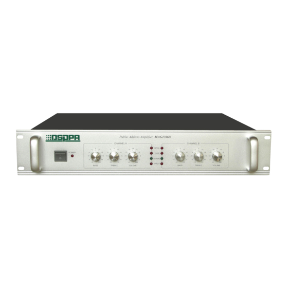
DSPPA MAG1306II Owner's Manual - Page 3
Browse online or download pdf Owner's Manual for Amplifier DSPPA MAG1306II. DSPPA MAG1306II 6 pages.

OPERATING PRECAUTIONS
Make sure the AC supply voltage is correct, it means the AC supply voltage must be as the
same as that printed on the rear panel of the amplifier.
amplifier to improper AC supply voltage is not covered by the three-year warranty.
Make sure the power switch is off before making any input or output connections.
To prevent speaker damage, it is always a good idea to turn the attenuator to minimum
before turn-on the amplifier if there is a high level signal at its input terminal.
The protection light on while operation means faults (e.g. overload or short-circuit) happening.
The power should be cut off immediately and should not be turn on before correcting the
faults.
Before turn on the device, using OUTPUT VOLTAGE SWITCH to set up the output voltage
value which matches the rated voltage of connecting speakers. The switch cannot be moved
during the operation.
ADDRESS SETTING
In the MAG system, you can connect a total of 32 units of this equipment, equipment set-based link
address is to be distinguished from each device, the address in binary using 8 way jumper settings, as
shown below: Each jumper has three needle, with the jumper's two pins to take the above link is expressed
as a binary "1"; with the jumper to take the under two-pin connecting expressed as a binary "0." The first
device address code is 00001001, which means jumper settings shown in Figure 2; second address code is
00001010, the method of jumper settings shown in Figure 3; other equipment jumper setting method refer
to the first and second set way, and so on, the corresponding address code please refer to the attached pages
(Equipment & Address code corresponding Table).
0
1
(Fig.1)
Input Connections
Audio input connections are made
via either the 3-pinXLR-type
connectors (Figure 1) or
6.35mm sockets on
the rear panel.
0 0 0 0
0 0
1
1
(Fig.2)
3
Damage caused by connecting the
0 0
0 0
1
(Fig.3)
1
2
Ground (Ring)
3
Figure1 3-pin XLR-type
0
1
0
Signal (Hot)
