DSPPA MP9012 Operation Instructions Manual - Page 2
Browse online or download pdf Operation Instructions Manual for Amplifier DSPPA MP9012. DSPPA MP9012 11 pages. Public address system, mp3/tuner/integrated pa power amplifier

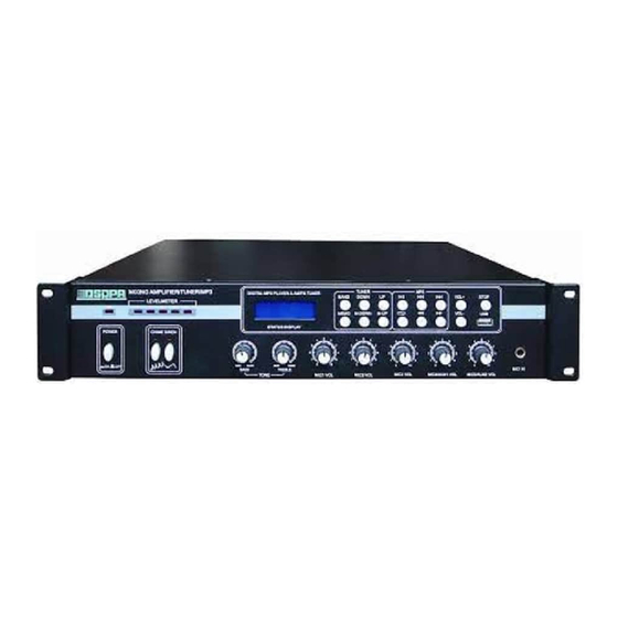
Front panel
MIXING AMPLIFIER/TUNER/MP3 MP9006
LEVELMETER
ON
2
4
6
POWER
CHIME 1
CHIME 2
ON
OFF
1
2
3
4 5
1. Power indicator
7. Treble adjust
2. Mains switch
8. Microphone volume adjust
3. LED level meter
9. Line 1/Microphone 4 volume adjust
4. Chime 1 button
10. Line 2/Microphone 5 volume adjust
5. Chime 2 button
11. No. 1 (priority) microphone jack
6. Bass adjust
12. Tuning/MP3 play status display screen
Remarks: It means overload distortion when 5 LED are normally bright, and it is necessary to adjust the
related volume control knob to make the 4-5th indicators flash.
Back panel
1
2
TUNER ANTENNA
GND
AM
FM(75 )
AUX1/MIC4 INPUT SELECT
AUX2/MIC5 INPUT SELECT
CHIME
VOL
AUX1
MIC4
AUX2
MIN MAX
MIC4
AUX1
AUX2
DSPPA Acoustic Technology Co.,Ltd.
9
10 11 12
131415 16
1. FM antenna jack
2. AM antenna jack
3. No. 2 microphone jack
4. No. 3 microphone jack
5. Phantom mains switch
6. 4 output terminals
Remarks: Among the four output terminals, it is only appropriate to use one pair of them.
12
DIGITAL MP3 PLAYER & AM/FM TUNER
8
10
MIN
MAX
MIN
BASS
TREBLE
TONE
6
7
3
4
5
MIC2 & MIC3 INPUT
PHANTOM
+24V
ON
OFF
AUX
EMC
MIC5
MIC5
OUT
IN
17
7. AC 220V fuse
8. Heat radiation blower window
9. Chime volume adjust knob
10. Auxiliary line 1/Microphone 4
convert switch
11. Microphone 4 jack
12. Auxiliary input (AUX) 1 jack
13
5
5
4
6
4
6
4
3
7
3
7
3
2
8
2
8
2
1
9
1
9
1
0
10
0
10
0
MAX
MIC1 VOL
MIC2 VOL
MIC3 VOL
8
13. Tuning status operation button
14. MP3 play status operation button
15. Tuning/MP3 volume increase button
16. Tuning/MP3 volume decrease button
17. Tuning/MP3 status stop button
18. USB movable disc port
6
7
COM
4Ω
70V
100V
F A
SPEAKER OUTPUTS
CAUTION!
RISK OF ELECTRIC SHOCK
~220V-240V/50Hz-60Hz/10A
DO NOT OPEN
请勿打开,以免触电
DSPPA
MP9006
MP9012
MP9025
MP9035
F A
F2AL
F4AL
F6AL
F6AL
18
2
14
15
16
17
18
5
5
5
6
4
6
4
6
7
3
7
3
7
8
2
8
2
8
9
1
9
1
9
10
0
10
0
10
MIC4/AUX1 VOL
MIC5/AUX2 VOL
9
10
8
13. Auxiliary input (AUX) 2 jack
14. Auxiliary line 2/ Microphone
5 convert switch
15. Microphone 5 jack
16. Line output port
17. EMC signal input jack
18. AC220V power cord
MIC1 IN
11
