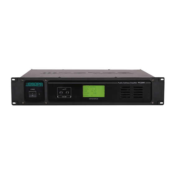
DSPPA PC2700 Owner's Manual - Page 3
Browse online or download pdf Owner's Manual for Amplifier DSPPA PC2700. DSPPA PC2700 4 pages. Public address amplifies

OPERATION:
1、INPUT:The entire input terminal is the XLR Input Socket in the rear panel.
(See pic.1)or 6.35mm Link Socket。
2 、 OUTPUT: The output terminals are in the rear panel.
Black terminal is COM and red terminal is HOT.
Normally we use Rated Power Terminal as Output. The
speakers shall be "rated power" when this distance is not long.
Accordingly, the amount of impedance of speakers shall be
4-16Ω.
3、
The system can be up to 256 equipments through address setting.
The address from 1-128 shall be used to be the normal sound
source. Address from 129-256
shall be used to be emergency
signal.
4、Automatically display in the LCD can shows "Normal",
"Open Circuit","Short Circuit","Emergency". The amplifier will be
cut off and give alarm signal automatically while the short circuit occur.
The emergency amplifier can adjust the volume to -10dB while alarm
input. The alarm signal can startup the amplifier while it's in the turn off situation. Amplifier can be turned off
again when the alarm is unchained.
5、Connect to the PC and use to PC to remote control the system.
OPERATING PRECAUTIONS
l Make sure the AC supply voltage is correct; it means the AC supply voltage must be as the
same as that printed on the rear panel of the amplifier. Damage caused by connecting the
amplifier to improper AC supply voltage is not covered by the three-year warranty.
l Make sure the power switch is off before making any input or output connections.
l To prevent speaker damage, it is always a good idea to turn the attenuator to minimum before
turn-on the amplifier if there is a high level signal at its input terminal.
l The protection light on while operation means faults (e.g. overload or short-circuit) happening.
The power should be cut off immediately and should not be turn on before correcting the faults.
SPECIFICATIONS
Model
PC1700
PC2200
3
Obverse Input
Reverse Input
Ground
6.35mm Link Socket
1
2
Obverse Inp ut
3
GND
Reverse Input
Pic. Figure1 3-pin
PC2700
