3onedata ICS6400-12GT12GS4XS Quick Installation Manual - Page 2
Browse online or download pdf Quick Installation Manual for Switch 3onedata ICS6400-12GT12GS4XS. 3onedata ICS6400-12GT12GS4XS 3 pages. Layer 3 industrial ethernet switch
Notice Before Mounting:
Don't place or install the device in area near water or
moist, keep the relative humidity of the device
surrounding between 5%~95% without condensation.
Before power on, first confirm the supported power
supply specification to avoid over-voltage damaging the
device.
The device surface temperature is high after running;
please don't directly contact to avoid scalding.
【DIN-Rail Mounting】
Adopt 35mm standard DIN-Rail mounting which is suitable for
most industrial scenes, mounting steps as follows:
Step 1
Check if the DIN-Rail mounting kit is installed firmly.
Step 2
Clip the upper part of the DIN-Rail mounting kit, i.e.
the fixed side, into the DIN rail.
Step 3
Press the lower side of the device and insert the
lower part of DIN-Rail mounting kit (the side with
spring support) into DIN-Rail.
Tips:
The DIN-Rail spring support is a metal sheet that can
move up and down, and there will be a sound after it is
clamped in.
Step 4
Check and confirm the product is firmly installed on
DIN rail, then mounting ends.
【Disassembling DIN-Rail】
Step 1
Power off the device.
Step 2
Use a slot type screwdriver or other tools to move
the DIN rail spring support downward; At the same
time, move the lower side of the device outward
and move out the lower part of the DIN rail
mounting kit.
Step 3
Lift the device upward slightly, move out the upper
part of DIN-Rail mounting kit. Disassembling ends.
Notice before power on:
Power ON operation: First insert the power supply
terminal block into the device power supply interface,
then plug the power supply plug contact and power on.
Power OFF operation: First, remove the power plug,
then remove the wiring section of terminal block. Please
pay attention to the above operation sequence.
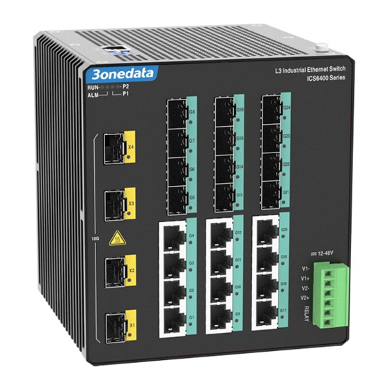
【Power Supply Connection】
The device provides 6-pin 5.08mm pitch power
supply terminal blocks and power supply occupies
the top 4 pins. It supports two independent DC
power supply systems, P1 and P2. The series of
device supports redundant power supply, two
power supply can work at the same time. The
device will still run non-stop when one power supply fails.
Power supply supports anti-reverse connection, which protect
the device from damage but the device cannot be powered on.
The definitions of power pin are shown in the left figure, and
the power input range is 12~48VDC.
【Relay Connection】
This device provides 6-pin 5.08mm pitch terminal
blocks, relay occupies the lower 2 pins. Relay
terminals are a set of normally open contacts of
the device alarm relay. They are open circuit in the
state of normal non alarm, closed when any alarm
information occurs. For example, they are closed
when powered off, and send out alarm. The switch supports 1
relay alarm information output that can output power supply
alarm or network abnormality alarm. It can be connected to
alarm light or alarm buzzer or other switching value collecting
devices, which can timely inform operators when the alarm
occurs.
【DIP Switch Settings】
The device provides 4-pin DIP switch for function
setting, in which "ON" is the enabled end. The
definitions of DIP switch are as follows:
DIP
Definition
Operation
1
Restore
Set the DIP switch to ON, the device
Factory
will root automatically and restore to
Settings
factory settings, then turn off the DIP
switch.
2-4
Reserved
—
【Console Port Connection】
The device provides 1 program debugging port
based on RS-232 serial port which can conduct
device
CLI
command
connecting to PC. The interface adopts RJ45 port, the RJ45
pin definition as follows:
Pin No.
2
3
Pin Definition
TXD
RXD
【Checking LED Indicator】
The device provides LED indicators to monitor its operating
status, which has simplified the overall troubleshooting
process. The function of each LED is described in the table
below:
LED
Indicate
Description
management
after
5
GND