3onedata IES1028-4GS-12F Quick Installation Manual - Page 2
Browse online or download pdf Quick Installation Manual for Switch 3onedata IES1028-4GS-12F. 3onedata IES1028-4GS-12F 3 pages. Unmanaged industrial ethernet switch
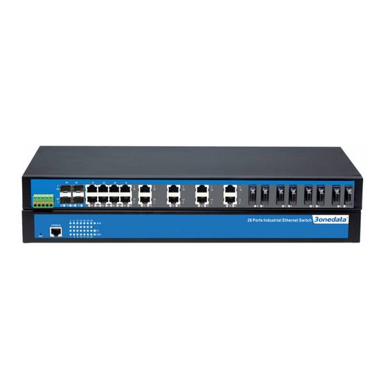
9.
Relay output terminal block
10.
Gigabit SFP slot
11.
Ethernet port connection indicator
12.
100M copper port
13.
100M fiber port
【Mounting Dimension】
Unit: mm
Attention before mounting:
Don't place or install the device in moist area or near
water, keep the relative humidity of the device
surrounding between 5%~95% without condensation.
Before power on, first confirm the supported power
supply specification to avoid over-voltage damaging the
device.
The device surface temperature is high after running,
please don't directly contact to avoid scalding.
【Installation of Rack-mounted Device】
Step 1
Select the device installation location to reserve
sufficient size.
Step 2
Adopt screws to install the mounting lugs in the
device position as figure below.
Step 3
Place the device in the rack, adopt 4 screws to
install the mounting lugs on the left and right side in
the rack.
Step 4
Check and confirm the product is firmly installed on
the rack, then mounting ends.
【Rack-mounting Device Disassembling】
Step 1
Power off the device.
Step 2
Unscrew the fixing screw of mounting lug on the
rack.
Step 3
Remove the device from the rack, disassembling
ends.
【Power Supply Connection】
This series of devices provide 5 pins 5.08mm pitch terminal
blocks, power supply occupies 3 pins on the left.The power
supply has nonpolarity and anti-reverse function, the device
can be normally working after reverse connection. The pin
definition of power supply as follows:
Pin NO.
1
2
Definition
L/+
GND
Single power supply
This series of products supports single
power supply scheme, power supply
value range is: 100~240VAC/DC.
Dual power supply
This series of products support dual
power supply scheme and provide P1
and P2 independent power supply
systems. When one of the power supply
system fails, the device can operate
uninterruptedly and normally, which has
improved the reliability of network operation. Power supply
value range is: 100~240VAC/DC.
Notes:
Power ON operation: First insert the power supply
terminal block into the device power supply interface,
and then plug the power supply plug contact and power
on.
Power OFF operation: First unpin the power plug, and
then remove the wiring part of terminal block, please
pay attention to the operation order above.
【Relay Connection】
This series of devices provide 5 pins 5.08mm pitch terminal
blocks; power supply occupies 3 pins on the left. Relay
terminals are a pair of normally closed contacts in device
alarm relay. They are open circuit in normal non alarm state,
closed when power off. This series of single and dual power
supply products respectively support 1 or 2 channels relay
alarm output and down alarm of power supply. Dual power
supply products will send out alarm when two power supplies
3
N/-