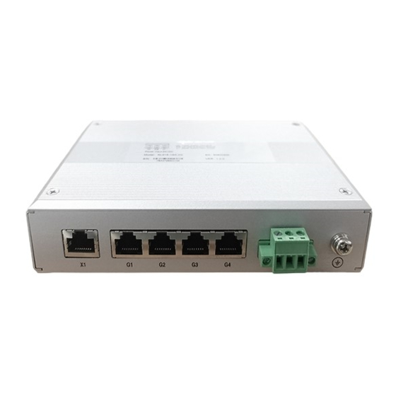
3onedata IES215-1GX-4G Quick Installation Manual - Page 2
Browse online or download pdf Quick Installation Manual for Switch 3onedata IES215-1GX-4G. 3onedata IES215-1GX-4G 2 pages. Unmanaged industrial ethernet switch

Step 2
On the wall of device mounting, place the device on
the wall for reference or refer to the mounting
dimension to mark two screw positions.
Step 3
Nail M3 screws on the wall and keep 2mm
interspace reserved.
Step 4
Hang the device on two screws and slide
downward, then tighten the screw to enhance
stability, mounting ends.
【Wall-mounted Device Disassembling】
Step 1
Power off the device.
Step 2
Unscrew the screw on the wall about 2mm.
Step 3
Lift the device upward slightly; take out the device,
disassembling ends.
Notice before power on:
Power ON operation: First insert the power supply
terminal block into the device power supply interface,
then plug the power supply plug contact and power on.
Power OFF operation: First, remove the power plug,
then remove the wiring section of terminal block. Please
pay attention to the above operation sequence.
【Power Supply Connection】
The device provides 3-pin power supply input terminal blocks
and supports 1 DC power supply input which
supports
anti-reverse
overload protection. Voltage range: 24VDC
(12~36VDC)
【Checking LED Indicator】
The device provides LED indicators to monitor its operating
status, which has simplified the overall troubleshooting
process. The function of each LED is described in the table
below:
LED
Indicate
Description
PWR
ON
running normally
PWR
PWR
OFF
running abnormally
The
Blinking
normally
RUN
The system is not running or
OFF
running abnormally
ON
System is running abnormally
Ethernet port has established
ON
a valid network connection
Ethernet port is in an active
Link/Act
Blinking
network status
(X1, G1-G4)
Ethernet
OFF
established
connection
【Specification】
Panel
10Gigabit copper port
100/1000/10000BASE-T
(10Gigabit port)
(10Gigabit/Gigabit/100M
self-adaption)
Gigabit copper port
connection
and
Indicator
Switch Property
Backplane bandwidth
Packet buffer size
MAC Address Table
Power Supply
is
connected
and
Power range
Access terminal block
is
disconnected
or
Power Consumption
system
is
running
No-load
Full-load
Working Environment
Working temperature
Storage temperature
Working humidity
Protection grade
port
has
not
valid
network
10/100/1000Base-T(X)
self-adapting RJ45 port, half/full
duplex self-adaption or forced
working mode, support MDI/
MDI-X self-adaption
Power
indicator,
running
indicator, interface indicator
28G
2Mbit
16K
24VDC(12~36VDC)
3-pin 5.08mm pitch terminal
block
3.6W@24VDC
7.7W@24VDC
-40~75℃
-40~85℃
5%~95% (no condensation)
IP30(metal shell)
