3onedata IES308-P User Manual - Page 3
Browse online or download pdf User Manual for Network Router 3onedata IES308-P. 3onedata IES308-P 4 pages. Ies308 series industrial ethernet switch
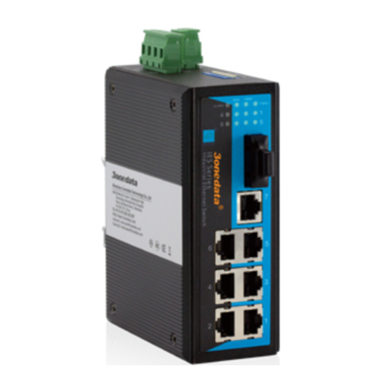
【LED Indicator】
LED indictor light on the front panel of product, the function of
each LED is described in the table as below.
System indication LED
LED
State
Description
Power is being supplied to power
ON
input PWR1
PWR1
Power is not being supplied to
OFF
power input PWR1
Power is being supplied to power
ON
input PWR2
PWR2
Power is not being supplied to
OFF
power input PWR2
When the alarm is enabled, power
ON
or the port's link is inactive.
Alarm
Power and the port's link is active,
OFF
the alarm is disabled.
System is not running well
ON/OFF
Run
System is running well
Blinking
ON
Port connection is active
Link/ACT
Data transmitted
Blinking
1~8
Port connection is not active
OFF
【Installation】
Before installation, confirm that the work environment meet the
installation require, including the power needs and abundant
space. Whether it is close to the connection equipment and other
equipments are prepared or not.
1. Avoid in the sunshine, keep away from the heat fountainhead or
the area where in intense EMI.
2. Examine the cables and plugs that installation requirements.
3. Examine whether the cables be seemly or not (less than 100m)
according to reasonable scheme.
4. Power: Redundant, dual 12-48VDC power input
5. Environment: working temperature: -40~75℃
Storage Temperature: -40~85℃
Relative humidity 5%~95%
DIN Rail Installation
In order to use in industrial environments expediently, the product
adopt 35mm DIN-Rail installation, the installation steps as below:
1. Examine the DIN-Rail attachment
2. Examine DIN Rail whether be firm and the position is
suitability or not.
3. Insert the top of the DIN-Rail into the slot just below the
stiff metal spring.
4. The DIN-Rail attachment unit will snap into place as shown
below.
Wiring Requirements
Cable laying need to meet the following requirements,
1. It is needed to check whether the type, quantity and
specification of cable match the requirement before cable
laying;
2. It is needed to check the cable is damaged or not, factory
records and quality assurance booklet before cable laying;
3. The required cable specification, quantity, direction and
laying position need to match construction requirements, and
cable length depends on actual position;
4. All the cable cannot have break-down and terminal in the
- 3 -
middle;
5. Cables should be straight in the hallways and turning;
6. Cable should be straight in the groove, and cannot beyond the
groove in case of holding back the inlet and outlet holes.
Cables should be banded and fixed when they are out of the
groove;
7. User cable should be separated from the power lines. Cables,
power lines and grounding lines cannot be overlapped and
mixed when they are in the same groove road. When cable is
too long, it cannot hold down other cable, but structure in the
middle of alignment rack;
8. Pigtail cannot be tied and swerved as less as possible.
Swerving radius cannot be too small (small swerving causes
terrible loss of link). Its banding should be moderate, not too
tight, and should be separated from other cables;
9. It should have corresponding simple signal at both sides of the
cable for maintaining.
【Specification】
Technology
Standard: Support IEEE802.3, IEEE802.3u, IEEE802.3x
Flow control: IEEE802.3x flow control, back press flow control
Exchange attribute
100M forward speed: 148810pps
100M maximum filter speed: 148810pps
Transmit mode: store and forward
System exchange bandwidth: 1.6G
MAC address table: 2K
Memory: 1M
Interface
Electric port: 10Base-T/100Base-TX auto speed control, Half/full
duplex and MDI/MDI-X auto detect
100M optic fiber port: 100Base-FX, SC/ST/FC connector, support
single mode (20/40/60/80Km optional), multi
mode (2Km), wavelength: 1310nm, 1550nm