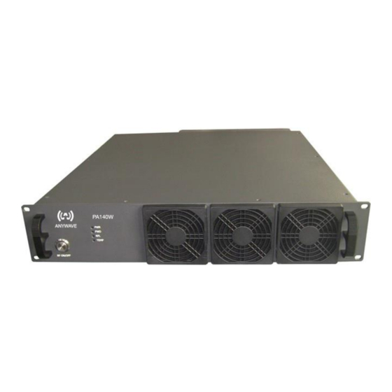
Anywave PA-140W User Manual - Page 7
Browse online or download pdf User Manual for Transmitter Anywave PA-140W. Anywave PA-140W 13 pages.

1.2 Back Panel
RF_IN
Connector:
Impedance:
Rated Power:
Note: If input power from RF_IN is lower than rated input value, the output power will be lower
than rated output power accordingly. This is because the PA has a fixed gain of 50 dB ± 1 dB. If
the input level from RF_IN is higher than the rated value, it will result in RF output distortion
and performance deterioration. If the input level is more than 1 dB higher than the rated value or
the output power is higher than 140 W, it may trigger the current-limiting function of the internal
power supply. The PA will enter the auto-protection mode, and there will be no RF output.
RF_OUT
Connector:
Impedance:
Rated Power:
Note: RF_OUT must be connected with a load, otherwise the PA will enter the auto-protection
mode and there will be in no RF output. Please note that the PA is designed to withstand any load
conditions, including no load at all, without damaging the PA. However it is strongly suggested
to have a load connected with proper impedance.
MONITOR (loop out of RF_OUT)
Connector:
Impedance:
Rated Power:
Note: It is OK to leave this port open without load.
RS232-A
Connector:
Note:
RS232-B:
Connector:
Note:
ACT-140PA-USR-DOC-V1.4, 09/12/2014
N
50 Ω
+1.76 dBm ± 1 dB
N
50 Ω
140 W (+51.46 dBm)
BNC female
50 Ω
+1 dBm ± 3 dB
DB9-M
Connected to REMOTE (RS232) port of ACT-5X, which is used
for control and communication between the PA and the exciter.
DB9-M
For customers' remote control to both the PA and the exciter (The
exciter REMOTE(RS232) port is connected to the PA RS232-A
port)
PA-140W User Manual
Page 7 of 13
