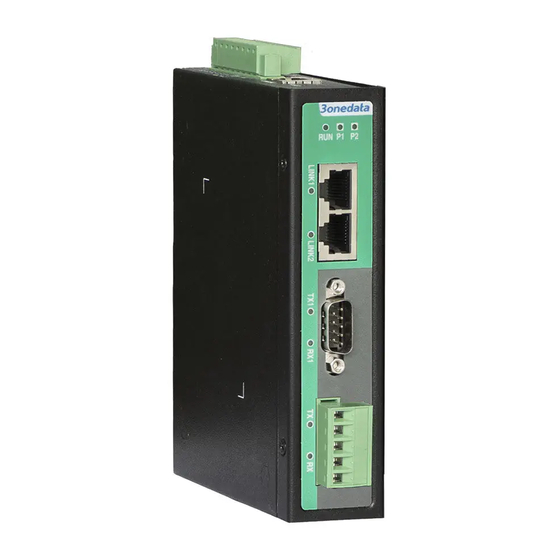
3onedata IGW1111-3IN1-DB Quick Installation Manual - Page 2
Browse online or download pdf Quick Installation Manual for Gateway 3onedata IGW1111-3IN1-DB. 3onedata IGW1111-3IN1-DB 3 pages. Industrial modbus gateway

moist, keep the relative humidity of the device
surrounding between 5%~95% without condensation.
Before power on, first confirm the supported power
supply specification to avoid over-voltage damaging the
device.
The device surface temperature is high after running;
please don't directly contact to avoid scalding.
【DIN-Rail Mounting】
Install the device
The product adopts 35mm standard DIN-Rail mounting, which
is suitable for most of the industrial scenes. Mounting steps as
below:
Step 1
Check whether the DIN-Rail mounting kit that
comes with the device is installed firmly.
Step 2
Insert the bottom of DIN-Rail mounting kit (one side
with spring support) into DIN-Rail, and then insert
the top into DIN-Rail.
Tips:
Insert a little to the bottom, lift upward and then
insert to the top.
Step 3
Check and confirm the product is firmly installed on
DIN-Rail, then mounting ends.
Disassemble the device
Step 1
Power off device.
Step 2
After lifting the device upward slightly, first shift out
the top of DIN-Rail mounting kit, and then shift out
the bottom of DIN-Rail, disassembling ends.
Notice before power on:
Power ON operation: First insert the power supply
terminal block into the device power supply interface,
and then plug the power supply plug contact and power
on.
Power OFF operation: First, remove the power plug,
and then remove the wiring section of terminal block.
Please pay attention to the above operation sequence.
【Power Supply Connection】
The device provides 8 pins
power supply input terminal
blocks, power supply occupies
4 pins in the left. It supports two
independent DC power supply
systems, P1 and P2, which
supports nonpolarity and anti-reverse connection function,
that the device can work normally after reverse connection.
Voltage range: 12~48VDC.
【Console Port Connection】
The device provides 1 channel procedure debugging port
based on serial port. The interface adopts RJ45 port which
can conduct device CLI command management after
connecting to PC.
Pin No.
2
Pin Definition
TXD
【Reset Button Setting】
This device provides 1 reset button, press the button for 4-5S
then release it to restore factory defaults.
【Console Port Connection】
This device provides 3IN1 serial port, which supports RS232,
RS485 and RS422 at the same time. The interface type is
DB9 and its pin definitions are as follows:
PIN
RS-232
RS-422
1
DCD
T+
2
RXD
T-
3
TXD
R+
4
5
6
7
8
9
【Checking LED Indicator】
The front panel LED indicators of this device monitor the
device working status with a comprehensive simplified
troubleshooting; the function of each LED is described in the
table as below:
LED
P1-P2
RUN
3
5
RXD
GND
LINK (1-2)
TX(1-2)
RS-485
D+
D-
RX(1-2)
-
DTR
R-
-
GND
GND
GND
DSR
-
-
RTS
-
-
CTS
-
-
-
-
-
Indicate
Description
PWR is connected and running
ON
normally
PWR is disconnected or running
OFF
abnormally
The system is running normally
Blinking
The system is not running or
OFF
running abnormally
System is running abnormally
ON
LAN port has established valid
ON
network connection
LAN port is in an active network
Blinking
status
LAN port hasn't established valid
OFF
network connection
No data or abnormal data is
OFF
being transmitted through serial
port
Blinking
Serial port is transmitting data
The port does not receive data or
OFF
receives data abnormally
