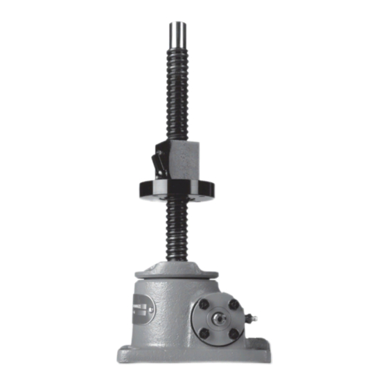
Duff-Norton AUM9821 Installation, Operation And Maintenance Instructions - Page 7
Browse online or download pdf Installation, Operation And Maintenance Instructions for Controller Duff-Norton AUM9821. Duff-Norton AUM9821 16 pages. Rotating ball screw actuators

2-1. Lubrication
Unless otherwise specified, actuators are
shipped packed with grease which should be suffi-
cient for one month of normal operation. For normal
operation the actuator should be lubricated once a
month, using Extreme Pressure grease Shell Oil Co.
Shell Albida LC EP #2 (Shell Product Code 70311).
This grease has been thoroughly evaluated in
Duff-Norton actuators and has demonstrated supe-
rior lubricating properties affecting both wear life
and maximum duty cycle. Duff-Norton is not aware
of an equivalent grease. If this grease is not
available in your area please contact your local
supplier for their recommendations. Greases con-
taining molybdenum disulfide should never be used.
For severe service conditions, the actuators
should be lubricated more frequently using the
above grease (daily to weekly depending on condi-
tions). If duty is heavy, an automatic lubrication
system is strongly recommended.
For most applications periodically lubricate the
rotating ball screws with a cloth dampened with a
good grade 10W30 oil. An instrument grade oil
should be used in dirty and heavy dust environ-
ments, while bearing grease is recommended for
operating environments at extremely high tempera-
tures. Extremes of temperature and other environ-
mental conditions should be referred to Duff-Norton
for recommended lubrication procedures.
Caution
Where the screw is not protected from
airborne dirt, dust, etc., do not leave a heavy
film of lubricant on the screw. Keep the ball
screw barely damp with the lubricant. Inspect at
regular intervals to be certain a lubricating film
is present. Ball screws should never be run dry.
2-2. Rebuild Procedure
Duff-Norton recommends the following proce-
dures for assembly and disassembly of actuators.
1. Tag critical parts to facilitate reassembly.
2. Mark all mating surfaces to ensure proper
meshing.
3. Clean and lubricate all parts as required.
4. All seals must be replaced when rebuilding.
5. All screws, washers and other small common
parts must be replaced if damaged in any way.
6. Replace damaged or frozen lubrication fittings
with new ones.
Section II
Maintenance
2-3. Required Tools
A bearing puller and press, soft jaw table clamp
and common hand tools are necessary for proper
assembly and disassembly.
2-4. Disassembly
Refer to Figure 3-1. When a numerical index
number is referred to, the reference is to Figure 3-1.
Disassembly should be accomplished on a clean
cloth.
1. Disassembly Inspection (Refer to Figure 3-1). To
determine the need for replacement of the ball
screw (5) or the lifting nut (24) the following
inspection should be made prior to disassembly
of the lifting nut from the ball screw: Inspect the
lifting nut assembly (24) and ball screw (5) as
follows:
a. Lubricate the lifting nut assembly and ball
screw . See paragraph 2-1.
b. Inspect the ball screw grooves for signs of
excessive wear, pitting, gouges, corrosions,
spalling or brinelling. It is usually less expen-
sive to replace the ball screw when any of
the above conditions exist. If you feel, how-
ever, that it can be reworked, return it to
Duff-Norton for final evaluation.
c. If none of the above conditions exist, check
backlash. Secure the ball screw in a table
clamp or similar fixture. Make sure that the
screw shaft cannot rotate. Push firmly on the
lifting nut assembly, first in one direction and
then in the opposite direction. This axial
movement of the lifting nut assembly is the
backlash. While making sure that neither
member rotates, measure the backlash with
a dial indicator.
Measure backlash at points of maximum
usage. Backlash of .001˝ to .010˝ is accept-
able.
d. If the backlash is over .010˝ and the ball
screw appears usable, replace ball nut.
2. Disassembly of Lifting Nut (24) From Ball Screw
(5) (Refer to Figure 2-2).
a. Refer to Table 2-1 and select a tubular arbor
with an I.D. slightly larger than the screw
pilot diameter. The arbor O.D. should allow it
to slide into the lifting nut between the screw
and the bearing balls. The arbor should be
Note
Note
7
