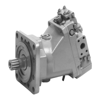
Danfoss 51 Series Service Manual - Page 8
Browse online or download pdf Service Manual for Controller Danfoss 51 Series. Danfoss 51 Series 11 pages. Bent axis motors
Also for Danfoss 51 Series: Service Kit Instructions (2 pages)

Service
Manual
Series 51
and
51-1
Motors
Service
Manual
Adjustments
Overview
...,fu
Warninq
This service
procedure may require disabiing the vehicle
1
machine
(raising
the wheels off the ground,
disconnectinq the
worl<
function,
arrd
so
forth) wlrile performing,
in
order
to
prevent injury to
the
technician
anc.l
bystanders.
T..ike
tlre
necessary safety
precautions
Adjust components of the
Series
51
and
Series
51-l
motors
perfollowing
procedures (where
necessary,
refer
to
Pressure
measuremenfs
on page
23,
for gauge
port
locations and
sizes):
Charge
pressure relief
valve
Set
the charge
pressure relief valve
to
the modelorder
code specifications.In most applications,
the
motorchargereliefvalveisset2to4bar [29to58psil
belowthesettingofthepumpchargereliefvalve
(measured
with
the
pump
in
its
neutral or zero-angle position).
This
setting
assumes
a
reservoir
temperature of
50"
Cl'122'F].
Charge pressure
is
referenced {additive)
to
case
pressure.
Measuring
charge
pressure
1. Install
a 0
to
60
bar
[0
to
t
000
psil
pressure
gauge in
port
Ml
or
M2
(use
which
ever
is
at
low
loop
pressure).
2.
Install
a
0
to
60
bar
[0
to
t
000
psil gauge in
port
Ll
or
L2
to
measure case pressure.
3.
Operate
the
system
with the
prime mover
at
normal operating
speed
and
the
pump at half stroke
(forward or
reverse).
Series
51
charge
pressure
relief valve
Adjustment
plug
"7
t
I
l16
lock
nut
i-*"1
l-t'l
l.'-'l
0't
208E
Older
Series
5'l
and
Series
51-1
motors may
be
equipped
with
an
externalscrew adjustable charge
pressure relief
valve (not shown).
Adjusting
charge
pressure
"dh
warning
Itrcorrect charge
pressure
setiings may resuit
in
the
inability
to build
required
system pressure and
/
or
inadequate loop flushinq flows.
You
must maintain
ihe
correct charge
pressure uncler all
operation
conditions
to
maintain pump performance
1.
Loosen
the
lock
nut using a
11/16 hex
wrench.
2, Turn the adjustment plug
with
a
large
screwdriverar
l3mm
hex
wrench.
,^A
\_-/
\@-
32
I
1
008567
.
Rev BA
.
June
201
4
