cashco SA5 Installation, Operation & Maintenance Manual - Page 2
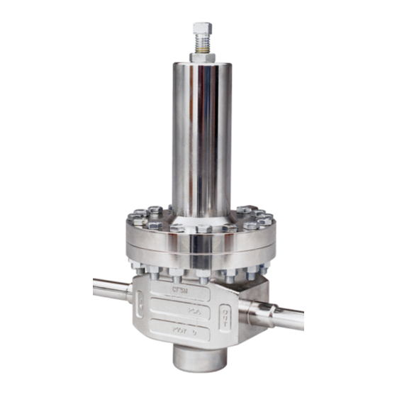
Browse online or download pdf Installation, Operation & Maintenance Manual for Controller cashco SA5. cashco SA5 12 pages. Ultra high purity, spring loaded back pressure regulators

IV. PRINCIPLE OF OPERATION
1. Movement occurs as pressure variations register
on the diaphragm. The registering pressure is the
inlet, P1, or upstream pressure. The range spring
op pos es di a phragm movement. As inlet pressure
drops, the range spring pushes the di a phragm
V. STARTUP
1
Start with the block valves closed.
2. Relax the range spring by turning the ad just ing
screw (1) CCW (viewed from above) a minimum
of three (3) full rev o lu tions. This reduces the inlet
(upstream) pres sure set point.
3. Crack open manual bypass valve to initially pres-
surize the system while simultaneously controlling
P
pressure through manual actuation of bypass
1
valve.
Do not walk away and leave a bypassed reg u la tor
unattended!
4. Closely monitor inlet (up stream) pressure via
gauge to ensure not over-pressurizing. NOTE: If
no bypass valve is in stalled, extra caution should
be used in start ing up a cold system; i.e. do ev-
erything slowly.
VI. SHUTDOWN
1. On systems with a bypass valve, and where sys-
tem pressure is to be maintained as the reg u la tor
is shut down, slowly open the bypass valve while
closing the inlet (up stream) block valve. Fully
close the inlet (upstream) block valve. (When on
bypass, the system pressure must be con stant ly
observed and manually regulated.)
Do not walk away and leave a bypassed reg u la tor
unattended!
2
CAUTION
CAUTION
SECTION IV
down, closing the port; as inlet pres sure increases,
the diaphragm pushes up and the port opens.
2. A complete diaphragm failure will cause the reg u-
la tor to fail close and fluid will discharge from the
spring chamber vent hole.
SECTION V
5. Open the outlet (downstream) block valve.
6. Slowly open the inlet (upstream) block valve to
about 25% open, observing the inlet (up stream)
pres sure gauge. Determine if the reg u la tor is
flowing. If not, slowly rotate the regulator ad just-
ing screw (1) CCW (viewed from above) until flow
be gins.
7. When flow is established steady enough that the
inlet (upstream) block valve can be fully opened,
begin to slowly close the bypass valve if installed.
8. Develop system flow to a level near its expected
normal rate, and reset the regulator set point by
turning the adjusting screw (1) CW to increase
inlet pressure, or CCW to reduce inlet pres sure.
9. Reduce system flow to a minimum level and
observe pressure set point. Inlet pressure will
increase from the set point of Step 7. The maxi-
mum build in inlet pressure on increasing flow
should not exceed the stated upper limit of the
range spring by greater than 30%. If it does,
consult factory.
SECTION VI
2. Remove range spring compression by turning
the adjusting screw (1) CCW to reduce the inlet
pressure.
3. Close the outlet (downstream) block valve.
4. Relieve the trapped upstream and down stream
pres sure.
5. The regulator may now be disassembled for
inspection and pre ven ta tive main te nance while
in-line.
IOM-CA5/SA5
