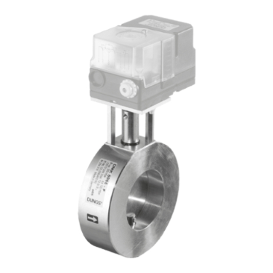
Dungs DMK 5100 Operation And Assembly Instructions - Page 2
Browse online or download pdf Operation And Assembly Instructions for Control Unit Dungs DMK 5100. Dungs DMK 5100 8 pages. Motor valve typ dmk

Einbaumaße / Dimensions / Cotes d´encombrement / Dimensioni [mm]
a
b
B
c
p
max.
DMK 5040 DN 40
500 mbar
DMK 5050 DN 50
500 mbar
DMK 5065 DN 65
500 mbar
DMK 5080 DN 80
500 mbar
DMK 5100 DN 100
500 mbar
DMK 5125 DN 125
max. Drehmomente/Flanschverbindung
max. torque/Flange connection
max. couple/Joint à brides
max. coppie/Collegamento a flangia
ISO 7005-2
Verschluß- und Verbindungsschrauben sachgemäß anziehen.
Werkstoffpaarung Druckguß – Stahl beachten!
Tighten plugs and union screws properly.
Make sure of proper material combinations, e.g. diecast – steel!
Serrer les vis fermeture et de fixation comme il convient.
Respecter l'appariement des materiaux moulage sous pression – acier!
Stringere in modo appropriato sia le viti di collegamento che quelle di chisura.
Prestare attenzione alla pressofusione in acciaio nell'abbinamento dei materiali.
max. Drehmomente / Systemzubehör
[Nm]
max. torque / System accessories
max. couple / Accessoires du système
max. coppie / Accessorio di sistema
Geeignetes Werkzeug einsetzen!
Please use proper tools!
Utiliser des outils adaptés!
Impiegare gli attrezzi adeguati!
Gerät darf nicht als Hebel benutzt werden.
Do not use unit as lever.
Ne pas utiliser la vanne comme un levier.
L'apparecchio non deve essere usato come leva.
DN
40
50
65
M
610
1100
1600
max.
T
200
250
325
max.
a
b
B
A
B
E
d
c
52
ø 6
76
A
B
C
D
Stellantriebe/Actuators
Servomoteurs/Attuatore
DMA 40 P.../...3
40
93
42
92
DMA 40 P.../...4
40
105
48,5
98,5
DMA 30 P.../...0
40
125
59,5
109,5
DMA 30 Q.../...3
40
140
67
117
DMA 30 Q.../...0
40
160
77
127
DMA 30 A.../...3
40
192
89,5
139,5
DMA 30 A.../...0
80
100
125
2400
5000 6000 [Nm] t ≤ 10 s
400
400
400
[Nm] t ≤ 10 s
a Stellanzeige für Klappenstellung.
Actuator display for valve position
Affichage de la position du papillon
Indicazione regolazione per posizione farfalla
b Arretierungsschraube für Motorwelle: Gewindestift ISO 4029-M5 x 6
Innensechskant SW2,5, Punkt 4, Seite 3 beachten!
Stop screw for motor shaft: Set screw ISO 4029-M5 x 6
Socket head screw SW2, item 4, refer to page 3.
Vis d'arrêt pour arbre du moteur: Tige filetée ISO 4029-M5 x 6
six pans creux SW2, point 4, respecter page 3!
Viti d'arresto per l'albero del motore: Vite filettata senza testa ISO 4029-M5 x 6
viti ad esagono incassato SW2, osservare il punto
c Bohrungen für Motorbefestigung: Zur Befestigung sind zwei Zylinderschrauben
M5 x 35 mit Muttern (selbstsichernd) erforderlich (nicht im Lieferumfang)
Holes for motor fixing: Two M5 x 35 pan-head screws with (self-locking)
nuts are required for fixing (not in scope of supply)
Perçage pour fixation du moteur: Pour fixer, on a besoin de deux vis
cylindriques M5 x 35 avec écrous (autobloquants)
(pas compris dans le détail de livraison)
Fori per il fissaggio del motorino: Per il fissaggio sono necessarie due viti
a testa cilindrica M5 x 35 con dadi (autobloccanti)
(non fanno parte della fornitura)
d Bohrungen für Motorbefestigung: Zur Befestigung sind vier Zylinderschrauben
M5 x 20 mit Muttern (selbstsichernd) erforderlich (nicht im Lieferumfang)
Holes for motor fixing: Four M5 x 20 pan-head screws with (self-locking)
nuts are required for fixing (not in scope of supply)
Perçage pour fixation du moteur: Pour fixer, on a besoin de quatre vis
cylindriques M5 x 20 avec écrous (autobloquants)
(pas compris dans le détail de livraison)
Fori per il fissaggio del motorino: Per il fissaggio sono necessarie
quattro viti a testa cilindrica M5 x 20 con dadi (autobloccanti)
(non fanno parte della fornitura)
E
F
IP40
65
IP40
65
IP40
65
IP54
90
136
IP54
90
136
IP65
80
120
IP65
80
120
M 16 x 65 (DIN 939)
Stiftschraube
Setscrew
50 Nm
Goujon
Vite per acciaio
M 4
M 5
M 6
M 8
2,5 Nm
5 Nm
7 Nm
15 Nm
Schrauben kreuzweise anziehen!
Tighten screws crosswise!
Serrer les vis en croisant!
Stringere le viti incrociate!
G
ø
Montage/Installation
Welle/Shaft
Montage/Montaggio
Arbre/Albero
c
99
66
8
c
99
114
8
c
99
114
8
d
149
10
d
149
10
c
124
10
c
124
10
G 1/8
G 1/4
G 1/2
5 Nm
7 Nm
10 Nm
T
max.
M
max.
T
max.
M
max.
G 3/4
15 Nm
2 ... 8
