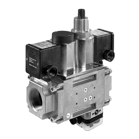
Dungs DMV-D/624 Installation Instructions Manual - Page 3
Browse online or download pdf Installation Instructions Manual for Control Unit Dungs DMV-D/624. Dungs DMV-D/624 9 pages. Dual modular nema 4x safety shutoff valves with proof of closure

Mounting
Setup
1. Examine the DMV valve for shipping damage.
2. The main gas supply must be shutoff before starting the
installation.
3. The inside of the DMV valve, the flanges, and piping must
be clean and free of dirt. Remove all dirt and debris before
installing the DMV valve. Failure to remove dirt / debris
could result in valve damage or improper performance.
Recommended Procedure to Mount the Flanges
1. Unpack the DMV valve and remove the bolts by using
13 mm wrench.
2. Remove the two protective covers.
3. Verify the o-rings and the grooves are clean and in good
condition.
4. Install the DMV valve with the gas flow matching the direc-
tion indicated by the arrows on the casting.
5. Mount the DMV solenoid from vertically upright to horizontal.
6. Clean the mounting surface of the flanges.
7. Mount the flanges to the DMV valve.
8. Tighten the screws in a crisscross pattern. See table for
recommended torque!
Recommended Torque
[Ib-in]
System Accessories
Recommended Piping Procedure
• Use new, properly reamed and threaded pipe.
• Apply good quality pipe sealant, putting a moderate
amount on the male threads only. If pipe sealant lodges
on the valve seat, it will prevent proper operation. If using
LP gas, use pipe sealant rated for use with LP gas.
Recommended Torque
[Ib-in]
for Piping
• On completion of work on the DMV valve, perform a leakage test. (See "Valve Leakage Test")
Painting Valve
• It is not recommended that this valve be painted. Painting
covers date codes and other labels that identify this valve.
• If the valve needs to be painted, a paint free of volitile organic
componants (VOC's) must be used. VOC's can damage
valve o-rings, resulting in external gas leakage over time.
Protection from Radiant Heat
• Radiant heat must be considered as a heat source that
could result in an ambient temperature higher than the rat-
ing of this valve.
3 ... 9
Installation position
If the flow is not in the same direction of the
arrows, the valves will not operate properly.
M8
134 lb-in
• Do not thread pipe too far. Valve distortion and/or mal-
function may result from excess pipe in the valve body.
• Apply counter pressure only a parallel jaw wrench only to
the flats on the flange when connecting to pipe.
• Do not overtighten the pipe. Follow the maximum torque
values listed below.
2"
1190
• During the painting process, use measures that will allow
the valve's date code and other labeling information to be
legible after the paint is dry.
• Provide proper shielding to protect against radiant heat.
Screw Size
[Ib-in]
NPT
pipe
[Ib-in]
