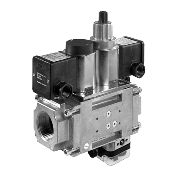
Dungs DMV-DLE/624 Installation Instructions Manual - Page 4
Browse online or download pdf Installation Instructions Manual for Control Unit Dungs DMV-DLE/624. Dungs DMV-DLE/624 9 pages. Dual modular nema 4x safety shutoff valves with proof of closure

Wiring
• Remove the junction box cover to expose the three termi-
nals
• The coil can be rotated to accommodate a conduit con-
nection in any position.
• Use only one of the knock-outs for connecting conduit to
the junction box. Support the opposite side of the junction
box when removing the knock-out.
• Run 14 or 16 guage wire rated for 95 °C (200 °F) through
the conduit and attach 1/2" NPT conduit to the junction box.
Valve Adjustment
Flow Setting
1. The valve is factory set with the flow adjustment fully open.
2. Locate the flow adjustment on top of valve 2. There are two
screws, the holding screw is recessed and has a blue seal-
ing compound on it, while the pan head screw prodtrudes
from the cap. Loosen the pan head screw until you can
freely rotate the flow adjustment. Turn clockwise for less
gas or counterclockwise for more gas. Check the flow at
the burner with an orifice or flow meter.
3. Tighten the pan head screw on the adjustment cap.
Initial Lift Adjustment (DMV-DLE only)
The initial lift adjustment varies the initial gas flow through the
valves as the valve seat begins to open. This adjustment can
vary the initial flow between 0 % and 70 % of the total gas
flow; 0 to 35 % of stroke. All DMV-DLE valves are factory set
with no initial lift. To adjust the lift proceed as follows:
4. Unscrew the small black cap on top of the silver hydraulic
brake to expose the initial lift adjustment knob.
5. The black cap also serves as tool. Turn the cap over and
insert it on the slot on the adjustment knob.
6. Turn the knob clockwise for a minimum initial lift or coun-
terclockwise for a maximum initial lift.
7. Once the desired initial fast lift has been achieved, reinstall
the black cap.
25 % Initial Lift
Valve Disc
Valve Seat
Flat area for support
15 % Initial Lift
75 % Slow Opening
25 % Fast Opening
• Use appropriate tools to connect the conduit fitting to the
junction box.
• Make electrical connections to the terminals using the wir-
ing diagram.
L2 (N)
• Replace junction box cover.
All wiring must comply with local electrical
codes, ordinances and regulations.
Max. Flow Adjustment
No Adjustment
DMV-D
Initial Lift Opening Curve
CFH
Initial Lift
Adjustment
Range
0 % Initial Lift
85 % Slow Opening
15 % Fast Opening
GROUND
L1
HOT
Initial Lift Adjustment
No Adjustment
DMV-DLE
100 % Slow Opening
T (s)
4 ... 9
