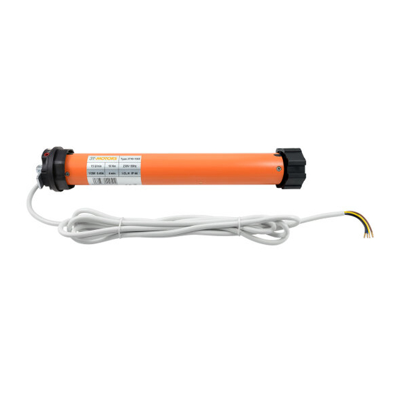
3T-Components 3T-MOTORS 3T45-SD Installation & Operating Instructions Manual - Page 9
Browse online or download pdf Installation & Operating Instructions Manual for Engine 3T-Components 3T-MOTORS 3T45-SD. 3T-Components 3T-MOTORS 3T45-SD 16 pages. Shutter motors with mechanical limit switches, for shafts from 60/40 mm

INSTALLATION INSTRUCTIONS
Remove shutter shaft:
3
Lower the roller shutter.
•
Open the cover of the roller shutter box.
•
Release the suspension springs from the roller shutter shaft.
•
Lift roller shutter shaft incl. ball bearing out of the holder.
•
Prepare motor for installation:
4
Push limit switch adapter flush against motor head.
•
Secure the shaft adapter with the supplied securing bracket.
•
Push the motor into the roller shutter shaft without using force (never knock it in). The fold of the shaft must lie over the recess in the shaft adapter.
•
Make sure that the roller shutter shaft is flush with the motor head limit switch adapter.
•
4.1
Motor head
Limit switch adapter
4.5
Roller shutter shaft
Mount bearings:
5
Remove old wall bearing on motor side (left or right installation possible).
•
Mount motor bearing at this point (2 mounting options: Universal bearing & cotter pin and cover cap bearing & securing clips / clip bearing).
•
Please mount the bearings so that the limit switches are freely accessible.
•
Make sure that the roller shutter motor with the shaft unit sits horizontally in the roller shutter box.
•
Mount motor with shaft unit:
6
Insert the motor head (with the entire shaft unit) into the motor bearing and secure it with the supplied cotter pin or securing clips (Cover cap bearing).
•
>
fig. 4.1 / 4.2
>
fig. 4.3 / 4.4
4.2
Fold
4.6
Recess
>
fig. 4.7 / 4.8
4.3
Securing bracket
4.7
wrong
>
fig. 4.5 / 4.6
Shaft adapter
4.4
Click
4.8
right
3T-MOTORS Tubular motors | Installation instructions
9
