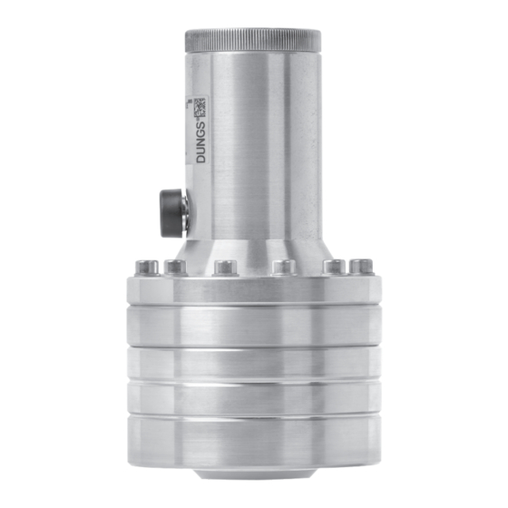
Dungs FRSBV 10005 ND User Manual - Page 13
Browse online or download pdf User Manual for Controller Dungs FRSBV 10005 ND. Dungs FRSBV 10005 ND 20 pages.

9.2 Description of installation
• Carry out the installation according to the
installation layout indicated below.
• Install the safety pressure relief valve in the
direction of flow (arrow / housing).
• Maximum flow velocity in the stabilisation section:
≤ 30 m/s.
• SBV drain pipeline 1" pipe.
Installation layout
1
Item
Designation
1
Input side shut-off valve (e.g. ball valve or shut-off flap)
2
Filter
3
Reducing adapter
4
Input side manometer
5
Controller
6
Stabilisation section
7
SBV
8
Ball valve
9
Output side manometer
10
Pressure tap
11
Pulse tap, SAV
12
Pulse tap, controller
13
Solenoid valve
14
Compensator
13 ... 20
2
4
3
5
• Prevent the accumulation of condensate: Lay the pulse
lines on an incline.
7
9
8
10
12
6
13
11
14
