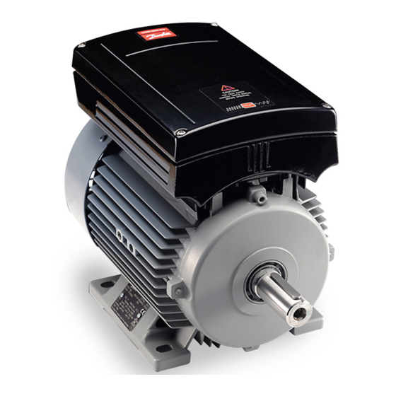
Danfoss FCM 300 Series Quick Setup - Page 2
Browse online or download pdf Quick Setup for Media Converter Danfoss FCM 300 Series. Danfoss FCM 300 Series 5 pages.
Also for Danfoss FCM 300 Series: Quick Setup (2 pages), Quick Setup (2 pages)

Factory setting
Reset
(pushbutton)
Start
Jog
Speed
reference
Fig. 1
-
Reset to be closed short time for resetting fault trips
-
Start to be closed for changing to run mode
-
Jog will run at fixed speed while closed (10 Hz)
-
Speed reference (0-10 V) determines speed while in
run mode
Terminals
1: Analogue input
2: Analogue input
3: Digital input
4: Digital input
5: Digital input
1 Mechanical installation
Install the FC motor with adequate access for routine
maintenance. Adequate space, particularly at the fan
inlet (50 mm), is necessary to facilitate airflow.
Where several FC motors are installed in close proximity,
care must be taken to ensure that there is no
recirculation of exhausted warm air.
NB!:
Ambient temperature
To avoid the FC part getting overheated, the
ambient temperature is not to exceed 40 °C and
the 24-hour average temperature is not to exceed 35
°C. If the ambient temperature is in the range of 40 °C -
55 °C, a reduction of the service life of the FC part is to
be expected. For further information, please see the
section on derating in the Design Guide.
NB!:
Bearings
Ball and roller bearings are despatched from the
works fully charged with grease. Shielded
bearings have sufficient grease for an operating life of at
least two years in normal ambient temperatures,
providing there is little or no leakage.
Tapping of fitments onto the motor shaft,
with a hammer or mallet, causes bearing
damage. This results in increased bearing
noise and a significant reduction in bearing
life.
Phone: 800.894.0412 - Fax: 888.723.4773 - Web: www.clrwtr.com - Email: [email protected]
VLT
®
DriveMotor FCM 300 Quick Setup
6: 24 V DC supply
7: 10 V DC supply
8: 0 V
9: Output
Motors type B14 & B34 mounting
1) Max length of the fixing bolts / screws
penetrating the B14 flange:
FCM 305-307 (frame 80) =
FCM 311-315 (frame 90) =
FCM 322-330 (frame 100) =
FCM 340 (frame 112) =
FCM 355-375 (frame 132) =
2) The following precautions must be taken:
a) A non-setting jointing and sealing compound must
be used to seal the bolt / screw threads in the motor
flange.
b) A soft copper washer must be inserted
underneath the bolt / screw head.
c) The joint face between the motor flange and the
mounting must be sealed using non-setting jointing
and sealing
compound.
For B34 types where it is only foot mounted, the flange
is not used. Then the bolts should be fitted in
accordance with parts a) & b) of item 2 to maintain the
IP55.
2 Electrical connections
Remove the inverter box cover, which is held by four
screws, to obtain access to the terminals.
Remove the detachable terminal plugs from the terminal
blocks X100 and X101 to obtain access to the mains
terminals.
Lift only the corner of the black plastic cover by the
cable entries to expose the mains terminals L
(see fig. 2).
The control cables must be screened cables.
Fig. 2
12.0mm
10.0mm
10.0mm
10,0mm
12.0mm
, L
and L
1
2
3
