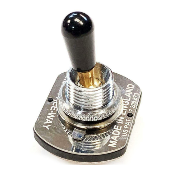
Free-Way Switch 3X3-03 Schematic Diagrams - Page 6
Browse online or download pdf Schematic Diagrams for Switch Free-Way Switch 3X3-03. Free-Way Switch 3X3-03 9 pages.
Also for Free-Way Switch 3X3-03: Schematic Diagrams (5 pages)

Note Vertical Orientation!
Any solder points
shown in between
pads are meant to
(B)
abridge both pads
(M)
(N)
Note: Neck & Bridge Vol controls are 'master' controls in this diagram, so that the Neck Vol mutes the entire output in positions 1,2 & 4
and the Bridge Vol mutes the entire output in position 2,3 & 6. The Middle Vol blends in the Middle Pickup in positions 4, 5 & 6.
If more scope for individual pickup blending is preferred, then reverse hot and wiper connections at B Vol and N Vol pots.
3X3-03
Free-Way Switch
Model No:-
HUMBUCKER COLOUR KEY
NORTH Start wire
1
NORTH Finish wire
2
3
SOUTH Finish wire
SOUTH Start wire
4
Vol
(Neck)
Pull for
Parallel
Multi-Core
Screened Cable
Grd To Bridge
Pull for
Pull for
Vol
Parallel
Parallel
(Mid)
Optional
DPDT
Tone
Switch
Vol
(Master)
(Bridge)
c
(Sleeve)
(Tip)
HHH + Parallel Switching 3V/1T
Notes:-
Optional Push/Pull Pot affects position 5 only: push in for middle
pickup only, pull out for Neck+Middle+Bridge pickups. Omit push/
pull pot and dotted wires for middle pickup only in position 5.
Use multi-core screened cable between switch and controls on
LP-style guitars.
Connect Pickup shield wires to pot casings.
The pickup colour coding shown in this diagram does not represent
any particular pickup manufacturer - please follow key.
Neck & Middle
4
1
5
2
Middle
3
6
(or option for 3 x pu.s)
Bridge & Middle
Scheme No 115 : Last Updated April B 2015
Neck
Bridge+Neck
Bridge
