AEV ACUO 908 Series Quick Manual - Page 12
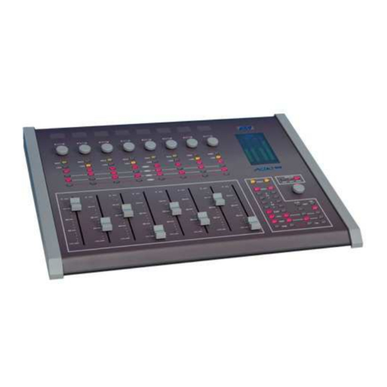
Browse online or download pdf Quick Manual for Music Mixer AEV ACUO 908 Series. AEV ACUO 908 Series 17 pages. On air broadcast console

Rear panel – connections
Head/USB/Logic & PWS
Microphone inputs connection
7
5
8
6
4
Line inputs connection
15
13
16
14
Outputs & Ausiliary connection
23
21
24
22
ACUO 908 Serie - AEV ON AIR CONSOLE
XLR Outputs
1
3
2
9
11
12
10
19
17
20
18
AEV Broadcast Srl, via della Tecnica 33 – 40050 Argelato (BO) Italy
Web site www.aev.eu
Telephone
Outputs & ausiliary
line
1 – Microphone 1 input XLR F connector.
2 - Trimmer adjusting the MIC 1 input level from 0 ÷
to +30 dB for very low volume microphones.
3 – Microphone 2 input XLR F connector.
4 - Trimmer adjusting the MIC 2 input level from 0 ÷
to +30 dB for very low volume microphones.
5 – Microphone 3 input XLR F connector.
6 - Trimmer adjusting the MIC 3 input level from 0 ÷
to +30 dB for very low volume microphones.
7 – Microphone 4 input XLR F connector.
8 - Trimmer adjusting the MIC 4 input level from 0 ÷
to +30 dB for very low volume microphones
9 – Line 1 input RJ45 connector.
10 – Line 2 input RJ45 connector.
11 – Line 3 input RJ45 connector.
12 – Line 4 input RJ45 connector.
13 – Line 5 input RJ45 connector.
14 – Line 6 input RJ45 connector.
15 – Line 7 input RJ45 connector.
16 – Line 8 input RJ45 connector.
17 – Dig1 & Dig2 input RG45 connector.
18- Control Studio Mutable output RJ45 connector
19 – External input RG45 connector.
20 – Control Room output RJ45 connector.
21 – AUX output RJ45 connector
22 – Control Studio output RJ45 connector.
23 – PGM Dig & UTLDig input RG45 connector.
24 – Remote Fader RG45 connector.
12
Microphone inputs
Line inputs
e-mail [email protected]
