aevit SMART-SHIFT Installation Manual - Page 15
Browse online or download pdf Installation Manual for Automobile Accessories aevit SMART-SHIFT. aevit SMART-SHIFT 16 pages.

3. CALIBRATION
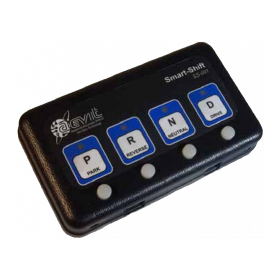
To calibrate the Smart Shift for your vehicle you will use the four gear selector keys and the two actuator control
buttons. The actuator control buttons are located on the front side of the controller on the left and right edges as
shown below. These two buttons are used to move the actuator in either direction when they are depressed, as
long as the ignition is "ON" and the brakes are applied. Once one of
the actuator control buttons is depressed, the actuator will move
in one direction and all four of the indicator lights on the touchpad
will illuminate to signify that you are in calibration mode. Use both
buttons to move the actuator to the desired position. Once the
actuator is positioned correctly, depress the corresponding button
on the touchpad.
IMPORTANT NOTE: If your vehicle is unable to reach all four of the Drive positions, program the un-used Drives for
the same setting as Drive. This way if the "D" key is pressed in error the actuator will still travel to the Drive position.
CALIBRATION PROCEDURE
Step 1: As discussed in the Actuator Installation section, in most installations the actuator will not meet the OEM
shift cable when the actuator is installed. For those cases you must first adjust the actuator to meet the OEM
shift cable. Confirm that the Electronic Connections section has been completed, and the vehicle's transmis-
sion is in Park. Turn on the ignition, start the vehicle, and apply and hold the brakes. (Remember the Smart-
Shift must receive a brake light input in order for the actuator to move.) Using the actuator control buttons,
position the actuator so that the OEM shift cable can attach to the actuator. Now, with the brake pedal de-
pressed, have someone attach the cable to the actuator according to the Installation section for your vehicle
type.
Step 2: With the engine still running and the brake depressed, use the Actuator Control Buttons to confirm that the
actuator can travel to the four main gears of the transmission (Park, Reverse, Neutral, & Drive). If not, some
adjustments to the placement of the OEM cable in relation to the bracket, or the OEM cable to the transmis-
sion will need to be made. If you are unable get the actuator to travel to these four positions, contact EMC
Service for assistance.
Step 3: After you have attached the cable and confirmed that the cable can travel to the required gear positions,
your ready to program the positions into memory. Remember, while in calibration mode all four LED's will
illuminate. Using the Actuator Control Buttons, place the vehicle in Park and press the "P" key to set the
position. The Park LED should now be the only LED illuminated. Park has now be set. Each time the "P" key is
depressed, the actuator will track to Park.
Step 4: Using the Actuator Control Buttons, place the vehicle in Reverse and press the "R" key. Again the LED above
the Reverse icon will illuminate. Repeat this same step for Neutral and Drive.
Step 5: For Drive2 follow the same procedure to set the position, except you will need to press and hold the "D" key
to set Drive2. Once Drive2 is set the "D" LED indicator will flash continuously. Press the "D" key or any other
key to change out of Drive2 and to move to the selected position.
Step 6: Once all gear positions have been adjusted, you will need to check the operation from both directions, that
is, from Park to Drive (or Drive1) and Drive to Park. The reason for this is that each shift position has an area
or "window" in which it will operate or "drop into" a gear. When you set the positions from Park to Drive you
positioned it on the high side of this area or "window". You must check to make sure that your high side ad-
justments are low enough to be activated from the low direction. If you are unable to "drop into" a gear from
the low side direction, use the actuator control buttons to reset the gears position slightly further to the low
side.
Actuator Control Buttons
SMART-SHIFT INSTALLATION
M1-1
13
