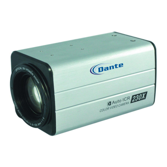
Dante DLF1102 Installation And Operation Manual - Page 4
Browse online or download pdf Installation And Operation Manual for Digital Camera Dante DLF1102. Dante DLF1102 10 pages. 1/4" 23x optical, 10x digital zoom 540tvl integrated camera

Components and accessories
1. 23X/30X integrate camera---------------------------------X1
2. Instruction manual-------------------------------------X1
3. 6-Pin connection cable-------------------------------X1
Install instruction
TELE
F-NEAR
SET
WIDE
5
1.Buttons
Following buttons control zoom, focus and auto focus function.
WIDE button: To widen the view .( ZOOM OUT)
TELE button : To close in on a far object.( ZOOM IN)
FFAR button : To see a far object clearly.
AF button
: To activate auto focus just once.
Print SET button locks the zoom control function of these buttons
and prompts the main setup menu.
Note:
The zoom position is saved after 5 seconds when you set zoom function.
Connection
Connector Function
Tele
Zoom
Wide
Near
Focus
Far
CCM
MD
* MD(Motion Detection ) output signal level (less than 10mA)
*
When using the MD function, the
to the frame ground.
Communication control connector
The camera can be controlled by using external controllers
like a remote controller.(RS-485 communication).
Number Name Description Number Name Description
1
GND
-
2
TRIGGER
3
EX-DN
- - -
2
POWER
VIDEO OUT
3
F-FAR
4
COMM
6
DC 12V IN
4
signal level
I/O
+6V~+12V
I
COM
COM
I
-6V~-12V
+6V~+12V
I
COM
COM
I
-6V~-12V
-
COM
+5V
O
0V
GND
should be connected
4
485 communication
485A
5
485B
485 communication
6
DC12V input
DC IN
6
Install instruction
Main setup menu can be navigated using these buttons
SET: to access the main setup menu
UP: (TELE button)
: To move the arrow indicator to up
DOWN(WIDE button): To move the arrow indicator to down
LEFT(FNEAR button) : To move the arrow indicator to left
RIGHT(FFAR button) : To move the arrow indicator to right
2. Power LED
illuminates when power is supplied
3. Video output socket
Used to connect the external video monitor in socket
4. Communication control connector
Used to connect the RS485 communication pin.
5. External control connector
Relates to the motion detection output signal.
Zoom and focus functions can be controlled using external signals
6. Power input Terminal
Power supply terminal (DC 12V 10%)
Cautions
Please connect the power once the installation is complete.
The wire is polarized. Match +
This camera use DC12V/500mA
Operating
Menu configuration
Main setup menu
CAM TITLE
OFF
WHITE BALANCE
ATW(OUTDOOR)
MANUAL
BACKLIGHT
OFF
HIGH
MOTION DET
OFF
FOCUS
MODE
ZOOM SPEED
DISP ZOOM MAG
LENS INIT
EXPOSURE
BRIGHTENESS
AGC
EXIT
SPECIAL
USER PRESET
DIS
IMAGE Addition
RESET
EXIT
and
-
terminals properly.
5
ON
AWC----SET
LOW
MIDDLE
ON
ZOOM TRK
D-ZOOM
ZOOM POS INIT
EXIT
IRIS
SHUTTER
SSNR
SENS-UP
DAY/NIGHT
PRIVACY
SYNC
COMM Addition
EXIT
7
