Belimo UGVL Series Quick Mount Visual Instruction Manual - Page 4
Browse online or download pdf Quick Mount Visual Instruction Manual for Control Unit Belimo UGVL Series. Belimo UGVL Series 4 pages. Linkage with lvk and svk series actuators

QUICK MOUNT VISUAL INSTRUCTION MANUAL
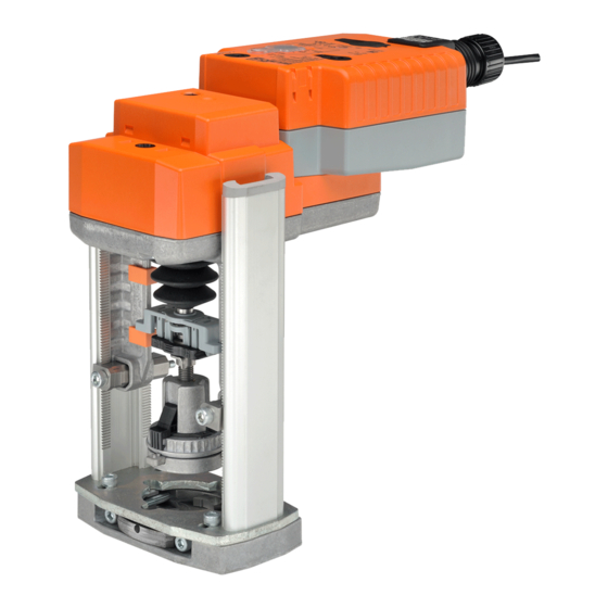
UGVL Linkage with LVK and SVK Series Actuators
WIRING DIAGRAMS
Electronic Fail-Safe Actuator with -3 and -SR
24 VAC Transformer
Blk (1) Common
Line
Volts
Red (2) + Hot
Wht (3) +
Pnk (4)
On/Off
100 to 240 VAC
Line
N L1
Blu (1) Common
Hot
Brn (2) +
H L2
Wht (3) +
On/Off
24 VAC Transformer
Line
Volts
Hot
Com
Controller
Triac Sink
Electronic Fail-Safe Actuator with MFT
24 VAC Transformer
Line
Blk
Volts
Red
Wht
(–)
2 to 10 VDC
Feedback Signal (+)
Org
On/Off
24 VAC Transformer
Blk
Line
Volts
Red
Ω 500 Ω
1/4 watt
(–)
Control Signal
(+)
Wht
VDC/mA
7
Org
VDC / 4 to 20 mA
2
3
18
–
Y input
1
Floating Point
A
2
–
Line
N L1
Hot
H L2
Floating Point
24 VAC Transformer
Line
Volts
10
5
18
Hot
Blk
Common
(1)
Red
+ Hot
(2)
Wht
Y
Input
(3)
1
Pnk
Y
Input
(4)
2
Controller
Triac Source
3
18
24 VAC Transformer
Line
Common
(1)
Volts
Hot
(2)
Y Input
(3)
2 to 10 VDC
U Output
(5)
Feedback Signal
Floating Point
3
18
24 VAC Transformer (AC Only)
Line
Common
(1)
Volts
+ Hot
(2)
Control Signal
(3) Y
Input, 2 to 10V
1
(5) U
Output, 2 to 10V
Functions
Min*
0%
Mid*
50%
Max*
100%
Normal**
Control mode acc. to Y
* Default selectable 0-100%. See Configuration Data Sheet.
** Customizable. See Configuration Data Sheet.
Override Control Min, Mid, Max Postions
18
A
2
100 to 240 VAC
Blu (1) Common
Brn (2) +
Wht (3) +
18
Com
Blk
Common
(1)
Red
+ Hot
(2)
Wht
(3)
Y
Input
1
Pnk
Y
Input
(4)
2
2
18
10
Blk (1) – Common
Red (2) + Hot
A
Wht (3) Y
Input
1
B
8
12
(–)
9
(+)
Org (5) U Output 2 to 10V
Direction of rotation switch
18
18
A
B
A
B
18
Blk
Common
(1)
Red
(2)
+ Hot
A
Ω
B
(–)
C
(+)
Wht
(3) Y
Input, 2 to 10V
VDC/mA
1
500 Ω
1/4 watt
7
Org
(5)
a
b
c
3
24 VAC Transformer
Line
Blk (1) Common
Volts
Red (2) + Hot
Ω
500 Ω
(–)
Control Signal
Wht (3)
(+)
Y Input, 2 to 10V
VDC/mA
7
(–)
2 to 10 VDC
Org (5)
U Output, 2 to 10V
Feedback Signal (+)
5
VDC / 4 to 20 mA
24 VAC Transformer
24 VAC Transformer
Line
Volts
Line
10
Volts
Blk
Hot
Com
Red
Wht
Pnk
Controller
Triac Sink with Separate Transformer
Notes:
Meets cULus requirements without the need of an
electrical ground connection
A
Actuators with appliance cables are numbered.
Actuators may be connected in parallel. Power
2
consumption and input impedance must be observed.
Actuators may also be powered by 24 VDC.
3
Only connect common to neg. (-) leg of control circuits.
5
A 500 Ω resistor converts the 4 to 20 mA control signal
7
to 2 to 10 VDC.
Control signal may be pulsed from either the Hot
8
(Source) or Common (Sink) 24 VAC line.
Contact closures A & B also can be triacs. A & B should
both be closed for the triac source and open for triac
9
sink.
For triac sink the Common connection from the actuator
must be connected to the Hot connection of the
controller. Position feedback cannot be used with a triac
10
sink controller. The actuator internal common reference
is not compatible.
IN4004 or IN4007 diode. (IN4007 supplied, Belimo Part
12
12
number 40155)
Actuators with plenum rated cable do not have numbers
18
on wires; use color codes instead.
18
18
(1)
Common
+ Hot
(2)
Y
Input
(3)
1
Y
Input
(4)
2
