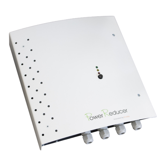
4-noks Power Reducer SA Quick Manual - Page 2
Browse online or download pdf Quick Manual for Audio & Video Accessories 4-noks Power Reducer SA. 4-noks Power Reducer SA 2 pages. Stand alone

GR I D
Mains meter
N
L
!
WARNING: CT orientation
Towards the
mains meter
Pag 2
INSTALLATION SCHEME
Immersion
Pantone 368C
C=57 M=0 Y=100 K=0
Power supply
connection
Mains CT
Green point
Towards the
residual-current
circuit breaker
Arrow and "L" pointing
towards the
residual-current
circuit breaker
Power Reducer
Pantone 158C
Grigio 70%
Nero
C=0 M=61 Y=97 K=0
C=0 M=0 Y=0 K=70
C=0 M=0 Y=0 K=0
Inverter
Power supply
connection
Generation
N
L
MAIN electrical panel
L
N
Household
Power Reducer - Wiring
Fuse 16A
Categ. FF
Terminal 1
Towards the immersion
meter
Current Transformer
Power Reducer - Terminals
Terminal 1 - Towards the resistive load (up to 3 kW)
1
L (phase)
2
GND
3
N (neutral)
Terminal 2 bis - clean contact - OPTIONAL
+10V
1
Ctrl
2
Power Reducer - LEDs and button
LED 1
LED 2
LED 3
Button
Pag 3
!
WARNING:
Terminal 3
label reporting the firmware
version uploaded:
it must be 1.2 o bigger
Terminal 2
!
WARNING:
Tripolar wire
Minumum dimension:
2,5 mm
2
16A
circuit breaker
Towards power
supply
Bypass switch
for system
override
(optional)
Terminal 2 - CT wiring
TA + (red or white wires)
1
2
TA - (black or brown wires)
Terminal 3 - Power supply
1
L (phase @ 230V)
2
GND
3
N (neutral)
Amount of energy passing through the CT
Amount of energy, expressed in %, of energy supplyed to the resistive load
(immersion) by the Power Reducer
> frequency = > power supplied
Bypass activated (manual boost or by the optional bypass switch)
Press the button to override the settings and switch on the immersion
for 1 hour (Boost)
Pag 4
