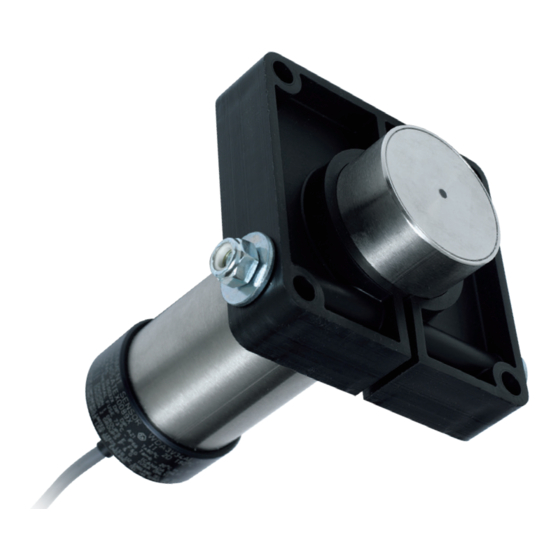
4B HTAS1V34 Operation Manual - Page 16
Browse online or download pdf Operation Manual for Accessories 4B HTAS1V34. 4B HTAS1V34 20 pages. Wda sensor belt alignment / motion & broken / slack chain monitor

SPEED RELAY WIRING DIAGRAM (SIMPLIFIED) -
The diagram below is a simplified wiring diagram for connecting the WDA sensor to a 4B Rotech Speed
Relay (Model SR2V5-1). See speed relay and other applicable instructions for complete set-up and
installation information.
110 VAC When Running
0 VAC When Stopped
110 VAC Supply
From Motor Starter
Fuse 2A
L
N
1 2 3 4 5 6
Speed Relay
Control Module
7 8 9 10 11 12
WDA Sensor
PAGE 16
SR2V5-1
Contacts Shown In
Underspeed / Stopped
State. Relay Energized
When Running And
De-energized If Speed
Falls Below The Set
Speed.
X
No Connection
Continuous Output
0 VDC Running
12/24 VDC Stopped
Insulate And Do
NOT Connect
