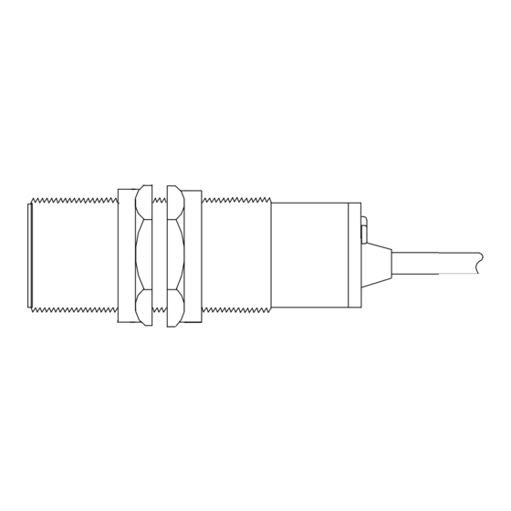
4B SLIPSWITCH M300 Installation Instructions Manual - Page 4
Browse online or download pdf Installation Instructions Manual for Monitor 4B SLIPSWITCH M300. 4B SLIPSWITCH M300 6 pages. Programmable underspeed monitor

Apply power to the machine and SLIPSWITCH.
Ensure that the machine has reached normal running
speed and then place the magnet on the 'Cal' point (located
on label on rear of unit), Count flashes of the green LED to
set the start delay required in seconds, then remove
magnet.
The output LED will echo the setting in seconds, during
which time, automatic calibration to 20% below normal
speed will be carried out.
Recalibration for a Different Setting
If the unit is to be used for a slower speed or with longer
time delay than previously set, the unit may trip out before it
can be calibrated. This can be avoided by applying power
while holding the magnet on the Cal point and removing the
magnet only when the machine has reached normal speed.
Wait for the green LED to illuminate permanently and then
recalibrate as above.
UV
UV
UV
UV
UV
1 2 3 4 5 6 7 8 9 0 1 2 3 4
1 2 3 4 5 6 7 8 9 0 1 2 3 4
1 2 3 4 5 6 7 8 9 0 1 2 3 4
1 2 3 4 5 6 7 8 9 0 1 2 3 4
1 2 3 4 5 6 7 8 9 0 1 2 3 4
1 2 3 4 5 6 7 8 9 0 1 2 3 4
1 2 3 4 5 6 7 8 9 0 1 2 3 4
1 2 3 4 5 6 7 8 9 0 1 2 3 4
1 2 3 4 5 6 7 8 9 0 1 2 3 4
1 2 3 4 5 6 7 8 9 0 1 2 3 4
1 2 3 4 5 6 7 8 9 0 1 2 3 4
1 2 3 4 5 6 7 8 9 0 1 2 3 4
1 2 3 4 5 6 7 8 9 0 1 2 3 4
1 2 3 4 5 6 7 8 9 0 1 2 3 4
1 2 3 4 5 6 7 8 9 0 1 2 3 4
1 2 3 4 5 6 7 8 9 0 1 2 3 4
<12
Supply
24-240V ac
12-240V dc
2VA
Low Risk
92
Output LED
Green
brown
blue
Dimensions (in mm)
30mm x 1.5mm
black/orange
black
black/red
Page 5 of 8
Sensing LED
Red
Connections
output Relay
3A 240V max
Non-inductive.
