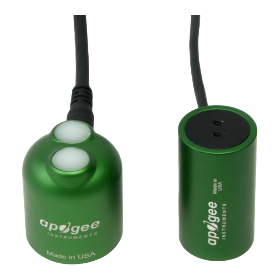
Apogee S2-121 Owner's Manual - Page 11
Browse online or download pdf Owner's Manual for Accessories Apogee S2-121. Apogee S2-121 16 pages. Pri sensors

CABLE CONNECTORS
Apogee sensors offer cable connectors to simplify the
process of removing sensors from weather stations
for calibration (the entire cable does not have to be
removed from the station and shipped with the
sensor).
The ruggedized M8 connectors are rated IP68, made
of corrosion-resistant marine-grade stainless-steel,
and designed for extended use in harsh
environmental conditions.
Instructions
Pins and Wiring Colors: All Apogee connectors
have six pins, but not all pins are used for every
sensor. There may also be unused wire colors
inside the cable. To simplify datalogger
connection, we remove the unused pigtail lead
colors at the datalogger end of the cable.
If you ever need a replacement cable, please
contact us directly to ensure ordering the proper
pigtail configuration.
Alignment: When reconnecting your sensor,
arrows on the connector jacket and an aligning
notch ensure proper orientation.
Disconnection for extended periods: When
disconnecting the sensor for an extended period
of time from a station, protect the remaining half
of the connector still on the station from water
and dirt with electrical tape or other method.
Tightening: Connectors are designed to be firmly
finger-tightened only. There is an o-ring inside
the connector that can be overly compressed if a
wrench is used. Pay attention to thread
alignment to avoid cross-threading. When fully
tightened, 1-2 threads may still be visible.
WARNING: Do not tighten the connector by
twisting the black cable or sensor head, only twist
the metal connector.
Inline cable connectors are installed 30 cm from the
(pyranometer pictured above)
A reference notch inside the connector ensures
proper alignment before tightening.
When sending sensors in for calibration, only send the
short end of the cable and half the connector.
Finger-tighten firmly
head
