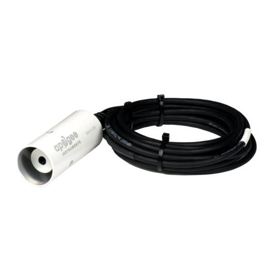
Apogee SI-411 Owner's Manual - Page 12
Browse online or download pdf Owner's Manual for Measuring Instruments Apogee SI-411. Apogee SI-411 20 pages. Infrared radiometer
Also for Apogee SI-411: Owner's Manual (20 pages), Owner's Manual (20 pages)

SDI-12 Interface
The following is a brief explanation of the serial digital interface SDI-12 protocol instructions used in Apogee SI-400
series infrared radiometers. For questions on the implementation of this protocol, please refer to the official
version of the SDI-12 protocol:
Overview
During normal communication, the data recorder sends a packet of data to the sensor that consists of an address
and a command. Then, the sensor sends a response. In the following descriptions, SDI-12 commands and
responses are enclosed in quotes. The SDI-12 address and the command/response terminators are defined as
follows:
Sensors come from the factory with the address of "0" for use in single sensor systems. Addresses "1 to 9" and
"A to Z", or "a to z", can be used for additional sensors connected to the same SDI-12 bus.
"!" is the last character of a command instruction. In order to be compliant with SDI-12 protocol, all commands
must be terminated with a "!". SDI-12 language supports a variety of commands. Supported commands for the
Apogee Instruments SI-400 series infrared radiometers are listed in the following table ("a" is the sensor address.
The following ASCII Characters are valid addresses: "0-9" or "A-Z").
Supported Commands for Apogee Instruments SI-400 Series Infrared Radiometers
Instruction Name
Send Identification Command
Measurement Command
Measurement Command w/ Check
Character
Change Address Command
Concurrent Measurement Command
Concurrent Measurement Command w/
Check Character
Address Query Command
Get Data Command
Make Measurement Command: M!
The make measurement command signals a measurement sequence to be performed. Data values generated in
response to this command are stored in the sensor's buffer for subsequent collection using "D" commands. Data
will be retained in sensor storage until another "M", "C", or "V" command is executed. M commands are shown in
the following examples:
Command
Response
aM! or aM0!
a0011<cr><lf>
aM1!
a0012<cr><lf>
aM2!
a0012<cr><If>
aMC! or aMC0!
a0011<cr><lf>
aMC1!
a0012<cr><lf>
aMC2!
a0012<cr><If>
http://www.sdi-12.org/specification.php
Instruction Syntax
aI!
aM!
aMC!
aAb!
aC!
aCC!
?!
aD0!
Response to 0D0!
Target temperature
Target temperature and sensor body temperature
Target millivolts and sensor body temperature
Target temperature w/ CRC
Target temperature and sensor body temperature w/ CRC
Target millivolts and sensor body temperature w/CRC
(version 1.4, August 10, 2016).
Description
Send Identification Information
Tells the Sensor to take a Measurement
Tells the Sensor to take a Measurement and return it
with a Check Character
Changes the Address of the Sensor from a to b
Used to take a measurement when more than one
sensor is used on the same data line
Used to take a measurement when more than one
sensor is used on the same data line. Data is returned
with a check character.
Used when the address is unknown to have the sensor
identify its address
Retrieves the data from a sensor
