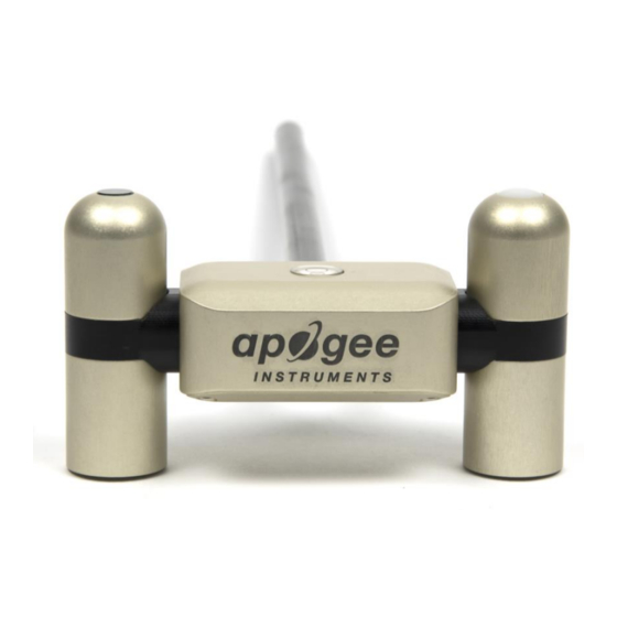
Apogee SP-510-SS Owner's Manual - Page 7
Browse online or download pdf Owner's Manual for Measuring Instruments Apogee SP-510-SS. Apogee SP-510-SS 19 pages. Net radiometer

Pyrgeometers (Longwave Radiation) SL-510 and SL-610
Sensitivity
Calibration Factor
(Reciprocal of Sensitivity)
Calibration Uncertainty
Measurement Range
Measurement Repeatability
Long-term Drift (Non-stability)
Non-linearity
Detector Response Time
Field of View
Spectral Range
Temperature Response
Window Heating Offset
Zero Offset B
Tilt Error
Uncertainty in Daily Total
Temperature Sensor
Output from Thermistor
Input Voltage Requirement for Thermistor
Calibration Traceability
Apogee SL-510 and SL-610 pyrgeometers are calibrated against the mean of at least two Apogee model SL-510
transfer standard pyrgeometers inside a custom blackbody cone held at multiple fixed temperatures over a range
of radiometer (detector and sensor body) temperatures. The temperature of the blackbody cone is measured with
replicate precision thermistors thermally bonded to the cone surface. The transfer standard pyrgeometers are
calibrated against the mean of least two reference upward-looking pyrgeometers under all sky conditions in Logan,
Utah. Each of the two reference pyrgeometers are recalibrated on an alternating year schedule (one instrument
per year) at the National Renewable Energy Laboratory (NREL) in Golden, Colorado. NREL reference standards are
calibrated to the World Infrared Standard Group (WISG) in Davos, Switzerland.
Net Radiometer
Input voltage Range
Average Max Current Draw (12 V DC power)
Response Time
Heaters (4 sensors individually heated)
Operating Environment
Dimensions
Mass
Cable
SL-510-SS (upward-looking)
-2
0.12 mV per W m
(variable from sensor to sensor, typical value listed)
-2
8.5 W m
per mV (variable from sensor to sensor, typical value listed)
-200 to 200 W m
Less than 2 % change in sensitivity per year
30 kΩ thermistor, ± 1 C tolerance at 25 C
0 to 2500 mV (typical, other voltages can be used)
2500 mV excitation (typical, other voltages can be used)
5.5 to 24 V DC (heaters are optimized to run at 12 V DC)
It takes 750 ms to digitize all detector signals
62 mA current draw and 740 mW power requirement at 12 V DC
-50 to 80 C; 0 to 100 % relative humidity
116 mm length, 45 mm width, 66 mm height
320 g ( with mounting rod and 5 m of lead wire)
M8 connector (IP68 rating) to interface to sensor housing, 5 m of four conductor, shielded,
twisted-pair wire, TPR jacket (high water resistance, high UV stability, flexibility in cold
SL-610-SS (downward-looking)
± 5 %
-2
(net longwave irradiance)
Less than 1 %
Less than 1 %
Less than 0.5 seconds
150°
5 to 30 µm
Less than 5% from -15 to 45 C
Less than 10 W m
-2
Less than 5 W m
-2
Less than 0.5 %
± 5 %
SN-500-SS
Heaters on: 72 mA;
Heaters off: 13.5 mA
conditions), pigtail lead wires
