Apogee DA-16 Owner's Manual - Page 11
Browse online or download pdf Owner's Manual for Media Converter Apogee DA-16. Apogee DA-16 17 pages. 24-bit 16-channel d/a converter
Also for Apogee DA-16: Datasheet (1 pages)

Congratulations! You have just purchased a powerful and flexible multichannel digital-to-analog converter that
renders an accurate soundstage and pristine audio quality in the tradition of Apogee's award-winning convert-
ers. While the DA-16 is simple in operation, you should take a moment to read over this manual in order to get
acquainted with the DA-16's features and operation.
Designed for the latest hard-disk recording systems, the DA-16 "IntelliDAC" offers 16 channels of Apogee
quality at an exceptionally affordable price, handling 24-bit D/A conversion at sample rates up to 96 kHz. The
converters can source their digital input from either AES/EBU, ADAT optical or TDIF sources, and the unit can
then sync to word clock or a specified input.
ADAT and TDIF inputs are organized into two groups of eight, and channels 1-8 and 9-16 can have differ-
ent sources. In addition, the light-pipe inputs accept the Sonorus S/MUX protocol for sample-splitting high-res-
olution signals into optical interfaces, allowing access to all 16 channels – the first time this protocol has been
included on an Apogee converter.
The input sample rate is detected automatically, and a two-level "Lock" indicator shows "wide" (up to ±150
degrees) and "narrow" (5 degrees) lock. LEDs indicate signal status on each channel, with the LED intensity
modulated by the signal level to give an "analog-like" display. The balanced analog outputs are supplied in
groups of eight channels on 25-pin D connectors, in keeping with other Apogee D/A conversion systems using
these connectors (the pinout is the same as on Tascam systems).
The subtitle "IntelliDAC" relates to the converter's unique "intelligent" two-stage re-clocking system, a first
for Apogee. Apogee converters have traditionally excelled at removing jitter from the incoming clock signal,
but for extremely jittery input sources, more control is needed. The DA-16 solves this problem by utilizing two
clocks. A fast-responding "read" clock, with a wide locking range, fills a dedicated FIFO buffer, while an ultra-
low-jitter 'write' clock writes the data out of the buffer, and is used to clock the converters.
The advantage of this configuration is that both incoming clock and data are de-jittered. In addition, the
system is less sensitive to phase errors between synchronous digital sources. Errors up to plus or minus 150
degrees can be corrected, substantially reducing the chances of glitching, and enabling the DAC to offer supe-
rior performance even when the input signal is extremely unstable.
Controls, Connections and Operation
The Front Panel
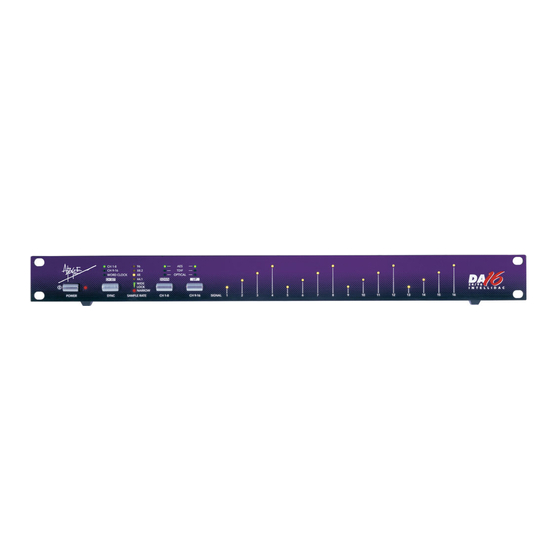
POWER
On the left-hand side of the front-panel is the POWER button. Press once to power the unit on and press again
to power off the unit.
SYNC/CHANNEL SET
To the right of the power button is the SYNC (momentary press)/CH SET (press & hold) button. This button has
two functions:
The SYNC function works in conjunction with the CH 1-8 and CH 9-16 buttons, allowing you to select the bank
of input channels (1-8, 9-16, or WORD CLOCK) used to synchronize the DA-16. Using the SYNC button, select
the sync source from either the bank 1 audio source, the bank 2 audio source, or the Word clock input on the
rear panel.
For example, let's say you have an ADAT connected to optical input 1-8 and a DA-88 connected to TDIF input
9-16 and you want the DA-16 to clock to the ADAT. You would select 'OPTICAL' using the CH 1-8 button and
'TDIF' using CH 9-16 button. Then you would select 'CH1-8' using the SYNC button. The DA-16 would
automatically lock to the sample rate of the incoming ADAT signal. In this scenario, if both recorders are to be
Apogee DA-16 User's Guide
Introduction
Page 11
