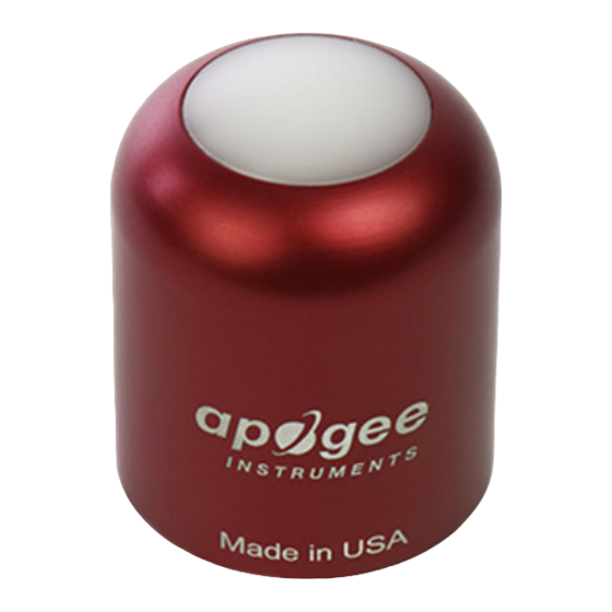
Apogee Instruments S2-432 Owner's Manual - Page 8
Browse online or download pdf Owner's Manual for Accessories Apogee Instruments S2-432. Apogee Instruments S2-432 18 pages. Red-far-red sensors

DEPLOYMENT AND INSTALLATION
Mount the sensor to a solid surface with the nylon mounting screw provided to prevent galvanic corrosion. To
accurately measure red and far-red photon flux density incident on a horizontal surface, the sensor must be level.
An Apogee Instruments model AL-100 Leveling Plate is recommended to level the sensor when used on a flat
surface or being mounted to surfaces such as wood. To facilitate mounting on a mast or pipe, the Apogee
Instruments model AL-120 Solar Mounting Bracket with Leveling Plate is recommended.
Nylon Screw: 10-32x3/8
Nylon Screw: 10-32x3/8
Model AL-120
Model AL-100
To minimize azimuth error, the sensor should be mounted with the cable pointing toward true north in the
northern hemisphere or true south in the southern hemisphere. Azimuth error is typically less than 1 %, but it is
easy to minimize by proper cable orientation.
In addition to orienting the cable to point toward the nearest pole, the sensor should also be mounted such that
obstructions (e.g., weather station tripod/tower or other instrumentation) do not shade the sensor. Once
mounted, the black cap should be removed from the sensor. The black cap can be used as a protective covering
for the sensor when it is not in use.
