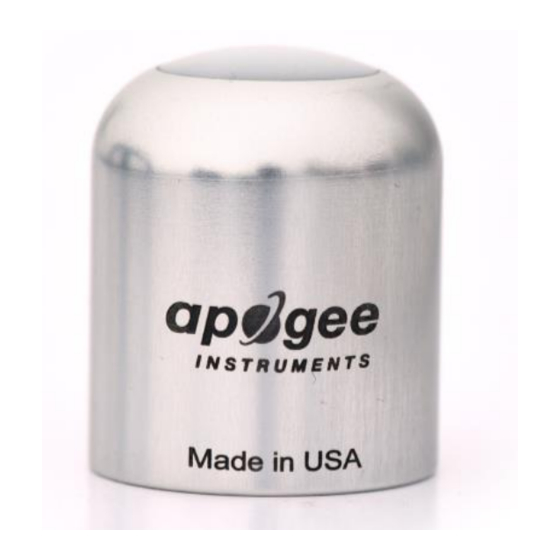
Apogee Instruments SU-205 Owner's Manual - Page 11
Browse online or download pdf Owner's Manual for Accessories Apogee Instruments SU-205. Apogee Instruments SU-205 18 pages. Ultraviolet-a sensor
Also for Apogee Instruments SU-205: Owner's Manual (18 pages)

OPERATION AND MEASUREMENT
Connect the sensor to a measurement device (meter, datalogger, controller) capable of measuring and displaying
or recording a millivolt signal (an input measurement range of approximately 0-2.5 V (SU-202) or 0-5 V (SU-205) is
required to cover the entire range of UV-A from the sun). In order to maximize measurement resolution and signal-
to-noise ratio, the input range of the measurement device should closely match the output range of the UV sensor.
The amplification circuit requires a power supply of 3.3 to 24 V DC (SU-202) or 5.5 to 24 V DC (SU-205). NOTE: to
prevent sensor damage, DO NOT connect the sensor to a power source greater than 24 V DC.
Wiring for SU-202 and SU-205
Black: Negative (signal from sensor)
Red: Power in (3.3-24 V DC or 5.5-24 V DC)
White: Output Signal
Clear: Shield
