Datakom DKG-175 User Manual - Page 8
Browse online or download pdf User Manual for Switch Datakom DKG-175. Datakom DKG-175 11 pages. Automatic transfer switch

DKG-175 User Manual
4. OPERATION OF THE UNIT
If 3-phases of mains voltage and frequency are withing limits and phase order is correct:
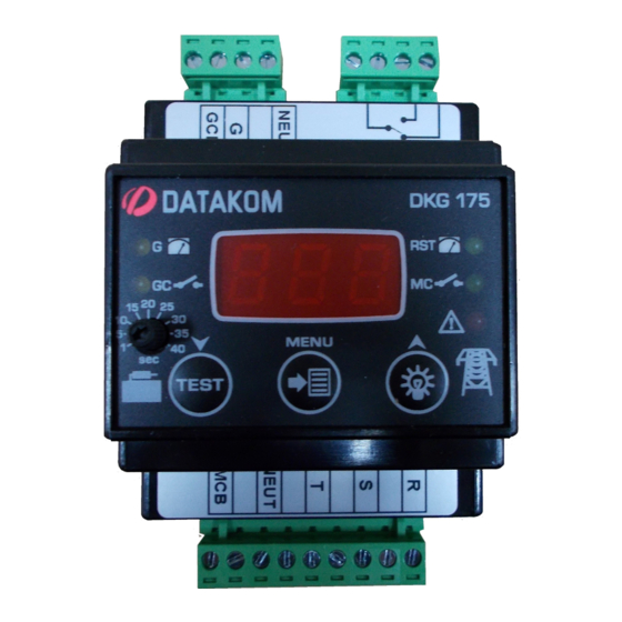
-MC, RST leds turn on.
-MCB terminal is supplied with voltage R.
-REMOTE START relay will be energised. (Normally closed and normally open contacts will switch
position.)
If any phase voltage or frequency goes outside of the limits:
-ALARM led turns on, RST led turns off.
-After the expiration of mains fail timer MCB terminal is open, MC led turns off.
-REMOTE START relay de-energises after engine start delay timer. (Contacts switch back to normal
positions) Generator must run.
When genset voltage is over the limit:
-G led turns on.
-GC led turns on after generator contactor timer. GCB terminal is supplied with voltage G.
When mains voltages and frequency are inside the limits:
-RST led turns on.
-ALARM led turns off.
-After the expiration of mains waiting timer, GCB terminal is open.
-After the expiration of mains contactor timer, MC led turns on, MCB terminal is supplied with voltage R.
-After expiration of Cooldown timer (Cooldown timer starts counting when GCB terminal is open)
REMOTE START relay energises. (Normally closed and normally open contacts will switch position.)
4.1 Test Mode
Test mode will be active if
blinks, remote start relay will be deactive and generator is expected to start. Test mode will be disabled
at the end of test mode timer.Test mode will also be disabled by holding pressed the
seconds before expiration of test mode timer.
button is held pressed for 2 seconds on operation mode. ALARM led
V-1
(24.07.2017)
button for 2
- 8 -
