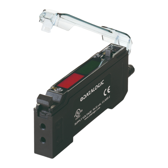
Datalogic S70-5-E3-NI Quick Start Manual
Browse online or download pdf Quick Start Manual for Accessories Datalogic S70-5-E3-NI. Datalogic S70-5-E3-NI 10 pages. Analogue output

For complete technical information about this product, including dimensions, accessories, and specifications, see www.datalogic.com.
WARNING: Not to be used for personnel protection
Never use this device as a sensing device for personnel protection.
Doing so could lead to serious injury or death. This device does not include the self-checking redundant circuitry
necessary to allow its use in personnel safety applications.
A sensor failure or malfunction can cause either an energized or de-energized sensor output condition.
Model
S70-5-E3-PV/NV
S70-5-E3-PI/NI
1
NOTE: Maximum sensing range in opposed mode at 12 ms response speed using 1mm diameter core plastic fiber.
CONNECTIONS
NPN Version
1
3
A_Out
2
LOAD
D_Out
4
LOAD
NOTE: Open lead wires must be connected to a terminal block.
S70 Analogue Output
Advanced sensor with dual digital displays
for use with plastic and glass fiber optic assemblies
Figure 1
Sensing Beam Color Reference Sensing Range
Visible Red
+
10-30 VDC (Current models)
12-30 VDC (Voltage models)
Input wire
1
2
3
4
5
6
7
1
Outputs
Voltage and PNP or
Discrete
2250 mm
Current and PNP or
Discrete
PNP Version
1
10-30 VDC (Current models)
3
12-30 VDC (Voltage models)
A_Out
2
LOAD
D_Out
4
LOAD
Input wire
1
Analogue and Discrete Output LEDs
CH1/CH2 Switch
RUN/PRG/ADJ Mode Switch
Lever Action Fiber Clamp
Red Signal Level
Green CH1 Analog Output
Signal or CH2 Threshold
+/SET/- Navigation key
Connector
NPN
4-pin,
M8 Pico-style
NPN
Key
1 = Brown
+
2 = White
3 = Blue
4 = Black
