CBE PRS300 BUS User Manual - Page 5
Browse online or download pdf User Manual for Controller CBE PRS300 BUS. CBE PRS300 BUS 12 pages. Solar charge regulator for photovoltaic modules
1
2
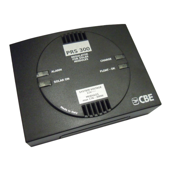
1)
Red led:
indicates a reverse polarity (wrong connection) of the photovoltaic modules and/or the
leisure battery.
2)
White led:
indicates that the regulator is on (without sunlight, the regulator turns off
automatically).
3)
Yellow led: indicates that the photovoltaic modules are charging the battery (step 1 and 2).
4)
Green led:
indicates the charge maintenance stage at a constant voltage (step 3).
Battery type
selector
Connector for
CBE BUS connection
Do not connect
IMPORTANT:
- The equipment shall be installed by qualified technical personnel only.
-
In case of misuse
, the warranty
any responsibilities for damage to things or persons.
- Exhausted batteries shall be disposed of according to
regulations in force.
- Solar System cables should be placed far away from the cables for Radio/TV/SAT antenna . s
Rated voltage 12Vd.c.
Photovoltaic module maximum open-circuit voltage (Voc): 27Vd.c.
Maximum output current: 18A.
Applicable panels: max 300W.
Self-consumption
Working temperature: -10°C +60°C.
3
Serial control with Mosfet.
Electronic device with reverse voltage block
4
Short circuits and reverse polarity electronic protection, for a
correct connection, please refer also to the diagram.
"PT 42" "PT 42" Test panel connection.
7
/
Set for the connection of 2 12V photovoltaic modules.
Dimensions (mm): 115x88 H37.
Weight (gr): 120.
A
C
B
12V
12V
of the device
:
: 0A (a
uto turn-off if sunlight is not present
6
200W
(max for each connection)
300W
(max total)
shall be void and the manufacturer declines
the
environmental protection
)
Photovoltaic modules (
and 12V leisure battery (
12V
connection
Connector for
selected
control panels
)
)
CBE
GB
5