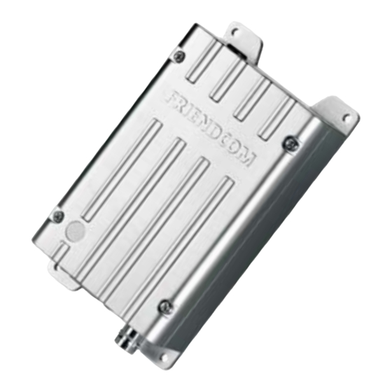
FRIENDCOM FC-302 U2 User Manual - Page 6
Browse online or download pdf User Manual for Transceiver FRIENDCOM FC-302 U2. FRIENDCOM FC-302 U2 20 pages.

Pin No.
Pin Name
On DB9
AUDIO_IN
1
(MOD IN)
AUDIO_OUT
2
(AF OUT)
PTT
3
GND
4
B+(9.6~16V
5
DC)
BUSY
6
MIC IN
7
SWITCH
8
SPK
9
TXD
-
(Radio)
RXD
-
(Radio)
CH1
-
CH2
-
CH3
-
CH4
-
4 Application Instruction
Functions of PC Personal Computer) software, hereafter called "FC-302 QuickSet v0.1.12 ", will be illustrated.
Main goal of this instruction is to save time for user by supporting exact usage of the software, at the same time,
give a help to user who wants to utilize the radio for another applications. This programming software enables
the various parameters of FC-302 to be read, modified, programmed and printed.
4.1 Hardware Installation
To apply PC software to radio application, FC-302 QuickSet En v0.1.12, programming cable, programming kit
and PC are needed. In this chapter, instruction for connection of the equipment will be illustrated.
Shenzhen Friendcom Technology Development Co., Ltd.
Pin No. on
DB15
Audio
input.
1
sensitivity is 100mW
Audio output; 3Khz LPF; Output level at
2
60% frequency deviation is 100±30mV. This
line has an internal pull-up resistor to +5V.
TX control,active low, only when PTT is
3
active AUDIO_IN and MIC IN are effective.
This line has an internal pull-up to 5V.
Ground
4
Positive pole input from DC power; +12V
5
Logical level output to indicated whether a
6
carrier or not. Low lever = carrier , high
level=no carrier. This line has a pull-up to
+5V.
Microphones input.
7
Control output, 5V high level output when
8
active
Audio output from the audio amplifier, @ 8Ω
9
The serial data is output from this pin, used
10
for radio parameter setting,5V TTL
The serial data is input to this pin, used for
11
radio parameter setting,5V TTL
Select channel by Dip switch; the low bit of
12
4-bit binary code.
Select channel by Dip switch; the second bit
13
of 4-bit binary code.
Select channel by Dip switch; the third bit of
14
4-bit binary code.
Select channel by Dip switch; the forth bit of
15
4-bit binary code.
Table 2
Description
3Khz
LPF;
Modulation
6
Remark
AUDIO_IN is effective only when
PIN 7(MIC) is vacant or with +5V
high level. 3KHz LPF filter existed
in audio channel.
Also able to work as simulated
serial port for parameter setting.
Can directly connect to electrets
MIC, the DC voltage of this pin
should lower than 3.5V, then MIC
transmission can be activated.
Also able to work as simulated
serial port for parameter setting.
SPK is effective when Pin 7
connect to MIC or GND, ( MIC PIN
power than 3.5V
Signal is output from radio.
Signal is input into radio
Available when channel control
mode is programmed as "by Dip
switch"
