COOK Gemini 2000 Series Installation, Operation And Maintenance Manual - Page 2
Browse online or download pdf Installation, Operation And Maintenance Manual for Fan COOK Gemini 2000 Series. COOK Gemini 2000 Series 8 pages. Ceiling and cabinet fans
Storage
If the fan is stored for any length of time prior to
installation, store it in its original shipping crate and protect
it from dust, debris and the weather.
Installation
Motor Installation
All Gemini units are shipped with motors mounted at the
factory.
Gemini 100 Inline to Ceiling Conversion
The Gemini 100 series can be converted from inline
to ceiling by ordering the Inline to Ceiling Conversion Kit
from Loren Cook Company (Part Number 797180). The kit
includes all parts required, plus detail instructions on how
to convert the Gemini 100.
Gemini 100 Ceiling to Inline Conversion
The Gemini 100 series can be field converted from
ceiling to inline by following these steps:
1. Remove and discard the inlet box end plate.
2. Install the inline cover panel with sheet metal screws
as shown on the following page. Ceiling to Inline
Conversion Kit can be ordered from Loren Cook
Company (Part Number 797181), or fabricate the
required part using the following two sketches.
18 Ga. Galvanized Steel
16-3/4
13-15/16
Bend up at 90
o
(Inches)
Flat Pattern
Inline
Cover
Panel
GEMINI IO&M
14-1/16
1-3/8
1-7/16
Finished Views
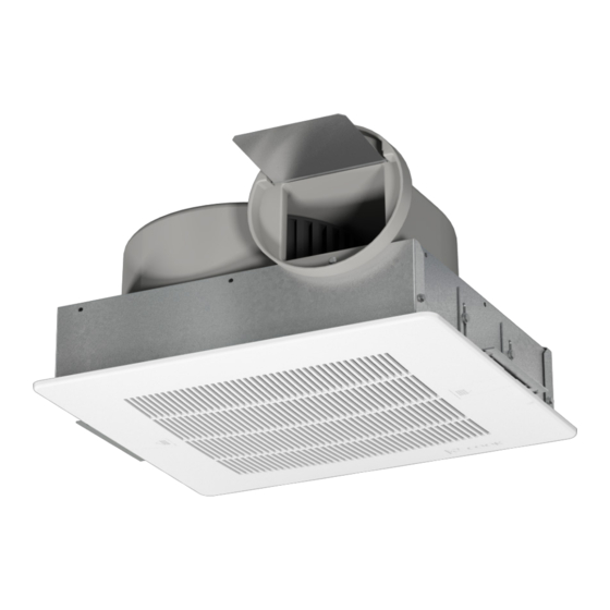
Direction of Discharge (200–900 Series)
Discharge direction can be converted from right angle to
straight line, without a kit, by swapping outer panel and the
inlet/grille: See Figure 1.
1. Remove the side panel, mounting brackets (2) and
grille (if present).
2. Place the side panel where the inlet/grille had been.
Place the mounting brackets on the edge where the
side panel had been. Holes are pre-punched for this
procedure.
3. Rotate unit so that the outlet is on top.
Start
Replace Parts
Inlet
Fan Installation
1. Use the mounting bracket slots to lower the unit
housing by a distance equal to the ceiling thickness.
Refer to Figure 2.
2. Raise the unit, as needed to accommodate acces-
sories and options: With optional filter, raise unit 3/8".
For both filter and deluxe aluminum grille options,
raise unit 7/8" to compensate for 1/2" grate protru-
sion of grille. If filter is not present: the grate on the
aluminum grille will fit inside of the unit (except sizes
160 & 180). Other grilles have no protrusion and fit
flush with the fan.
3. Fasten duct work to the outside of the duct collar
(damper frame) using sheet metal screws and foil
tape. Make sure sheet metal screws are placed
where they do not interfere with damper operation.
4. Fasten the housing to the bottom of the joists through
the holes provided in the mounting bracket.
For Ceiling Radiation Damper Installation
see separate document, "Gemini/CRD
Installation Supplement."
2
Figure 1
Outlet
Inlet
Remove Parts
x2
Outlet
B51111-002