Cooke Water Witch Installation Manual - Page 4
Browse online or download pdf Installation Manual for Water System Cooke Water Witch. Cooke Water Witch 6 pages. A fully automatic pool and spa water levelling system
Also for Cooke Water Witch: Installation & Setup Manual (12 pages)

SENSOR & SOLENOID CONNECTIONS
Transformer
Sensor Plug Three Position
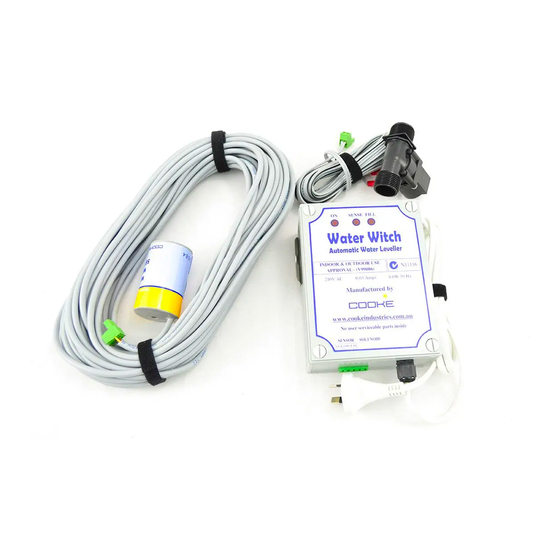
The Water Witch s designed to be installed close to the pool equipment. Both the
sensor and solenoid leads are normally 5 meters long with plugs attached for
connection to the base of the control box as shown. (Water Witch 20 & 30 for
Balance Tank installs come with 20 & 30 meter Sensor lead respectively).
Dip Switch
TX GRD RX Sol 1 Sol 2
Red
Yellow
Grey
Black & Green
Twisted together
Centre Position
Sensor Cable
If the standard cable length is
insufficient contact your Distribu-
tor as 20 & 30 Meter cables are
available ex Stock.
Custom Made lengths above this
can be manufactured.
DO NOT JOIN
THE CABLE
Solenoid Plug
Two Positions
Grey with Stripe
Cable Colour Code Reference
