AUSTRALIAN MONITOR AM1600 Owner's Manual - Page 4
Browse online or download pdf Owner's Manual for Amplifier AUSTRALIAN MONITOR AM1600. AUSTRALIAN MONITOR AM1600 8 pages. Professional audio power amplifier
Also for AUSTRALIAN MONITOR AM1600: Brochure (4 pages), Specification (2 pages), Operation Manual (20 pages)

I
I
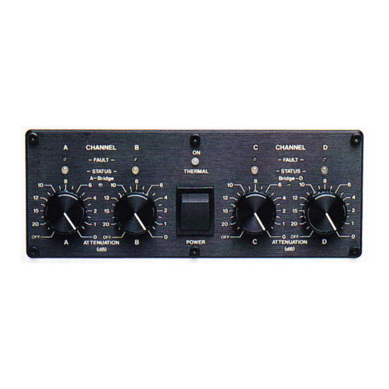
The 21 position detented ATTENUATORs can be used for level control,
but the
normal (and recommended) operating procedure is to run these at
fully
on
(fully
clockwise
- OdB
Attenuation) and to
use
the other equipment in the signal chain to
alter your gain structure.
[F
If full
output level is required, then you should NOT have the
AYTENUATORs
set
below the -10d8 label, otherwise distortion
in the
amplifiers preamp circuitry could
occur.
In the event
thatyou
need to
drive
70
-
120
Volt lines,
or
require more
porver
into
high
impedance loads, you may want to bridge your AM1600/f000
amplifier.
To bridge
the
amplifrer you
will
need
to
reverse
the
phase
polarity
of one of the
amplifier's channels.
Apply your input
to
CHANNEL
d
and channel A
will
then drive the positive
side
of
the speaker load. (This channel is the "In Phase" input and output).
A
Phase
Change lead is then used to strap
input
signal from
CIIANNEL
A
input
to
CHANNEL
B
input.
(See
diagram below for details of a Phase Change lead).
Now Channel B is receiving the
input
signal which is out of phase
with
Channel
A
The speaker load
is
then placed between the two
Red
Binding
Post
Output terminals.
Channel A Output
will
be
connected to
the positive (+) side
of
the load, and Channel
B Output to the negative C) side
of
the
load.
lIP
The ATTENUATOR.S shouldbe set to the same postion
on
both channels
(preferably the
OdB
Attenuation
-
fully
clockwise)
[F
When
bridgng
a
pair
of
channels, you must use the
RED binding
post
OUIPUTS
of those
channels. These two red connectors are the only
connections to
be
made to the speaker load. The same output can
be
found
by using Pin
3
from both
of
the XLR OUTPUTS.
F
Do
NOT
make any other connections at
all
to the speaker OUTPUT
terminals
or connectors.
NOTE:
Pin
2
on
conrpchr
A
goes to
p{n
3
on
@nrrclor
B.
(And
pin
3
on
@nnector
A goes
to
pin
2 on
onrcctor
B).
Channel A Visual Display
(foud
to
the left
of
the
power
sri@
(Channel
B is
a minor image of this).
A simple, yet thorough, Visual display
section
is found on the
Front
Panel
of
the
amplifrer. This
section
provides the user
with the
necessary
day-to-day function
of
an Output Level LED Ramp,
as
well
as
including various
circuitry
status
indicators.
To describe the indicators clearly, we
will
only discuss the
teft
hand
side of
the
unit
(also
known
as
Channel A), since the Riglrt hand side (Channel B) is
a
mirror
image
of
the
left,.
k
Poge 4
