Austria Email VT-N 1000-FFM Operating And Mounting Instructions Manual - Page 12
Browse online or download pdf Operating And Mounting Instructions Manual for Boiler Austria Email VT-N 1000-FFM. Austria Email VT-N 1000-FFM 16 pages. Pressure-proof large storage tank

10. Temperature Display, Temperature Control for Charge Pumps
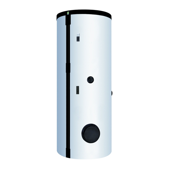
All devices are provided with two openings for the installation of a temperature display and/or a charge
pump control, which are sealed using a rectangular plastic cover in the condition as delivered. After
removal of this cover, a capillary thermometer (model ATH) or a combined capillary tube thermometer –
charge pump controller (accessory ATR) may be installed, as required. The double sensor channel for
uptake of the capillary sensors is provided with a cross-section for insertion of 2 ø7mm sensors or 1 x
ø7mm + 1 x 14 mm semi-circular sensors (see paragraph 10). In the event that controllers are installed,
it must be ensured that the boiler temperature cannot exceed 95° C in practical use.
11. First Commissioning
The tank must be filled with water before the heating is switched on.
The first-time heating up of the device must be monitored!
The expansion water created in the internal boiler during the heating process must drip from the safety
valve.
Automatic switching-off of the temperature controller, any electric heating unit or heat pump that may
be installed and/or the boiler must be checked.
Caution: the hot water drain pipe as well as parts of the safety fitting may become hot.
After completed heating-up, the set temperature, the actual temperature of the water withdrawn and
any temperature display that may be installed should correspond approximately.
Due to the hysteresis of the temperature control (± 7°K) and possible radiation losses (cooling-down of
the pipelines), the temperature specifications are subject to an accuracy of ± 10°K.
12. Decommissioning, Emptying
If the tank is taken out of operation or not used for a longer period of time, then it must be emptied
and disconnected all-pole (in the case of electric heating) from the electric power grid. Turn off the lead
switch or the automatic cutout.
In rooms with a permanent risk of frost, the water heater must be emptied before the start of the cold
season, insofar as the device remains out of operation for several days and is not operated in an anti-
frost setting.
The service water is emptied through the drain valve of the safety valve combination after closing the
shutoff valve in the cold water supply line and under simultaneous opening of all hot water valves of the
connected service fittings. Emptying may also be performed through the safety valve into the expansion
water funnel (drop collector). For this purpose, the safety valve wheel is turned to the »Test« position.
Caution: hot water may exit during emptying.
The tank is emptied up to the level of cold water inflow connecting piece. The residual water remaining
does not represent a risk, even in the case of frost.
In the case of a risk of frost, it must be observed also that not only the water in the water heater and
in the hot water lines can freeze, but also in all cold water supply lines to the service fittings and to the
device itself. Therefore, it is advisable to empty all fittings and lines holding water (also heating circuit =
heating coil) back to the frost-safe part of the domestic water system (domestic water supply).
If the tank is put back into operation, then it must bindingly be observed that it is filled with water and
that water exits bubble-free at the hot water valves.
The first heating process must be performed and monitored by a licensed expert.
Id.Nr.: 233754-4
12
