Bender B94060010 Quick Start Manual - Page 5
Browse online or download pdf Quick Start Manual for Controller Bender B94060010. Bender B94060010 12 pages. Charge controller
Legende
A
B
C
D
E
F
a
b
c
Weitere Anschlussmöglichkeiten des Ladereglers fin-
den Sie im Benutzerhandbuch.
i
Die RJ45-Benutzerschnittstelle ist nicht als
Ethernet-Schnittstelle ausgelegt.
i
Bei der Verwendung von Nano-SIM-Karten mit
einem entsprechenden SIM-Karten-Adapter
kann der SIM-Karten-Einschub beschädigt wer-
den. Daher wird empfohlen, nur Micro-SIM-
Karten zu verwenden.
i
Weitere Informationen zum Anschluss sind den
Handbüchern des Zubehörs zu entnehmen
(Bsp. W15BS).
• PE an „0V" anschließen; Referenzlevel für
Control Pilot (CP-Kommunikation) muss auf
demselben Pegel wie Energieversorgung lie-
gen (Normenreihe IEC 61851).
• Modbus (A, B) geschirmt anschließen; Schirm
an PE anschließen
• Leitungslängen (außer Modbus, Ethernet,
Power IN und Ladekabel): < 3 m, Leitungen
nur innerhalb der Wallbox/Ladestation und
nicht parallel zu Netzleitungen verlegen.
Anschluss Verriegelungsmotor
Anschlussbuchse Benutzerschnittstelle
Anschlussbuchse
Anschluss Stromwandler (CT)
Anschluss Benutzerschnittstelle (RJ45)
Anschluss Modbus/eHZ Zähler (RJ10)
RCD Typ A
Spannungsversorgung DC 12 V
Messstromwandler (CT) mit Stecker
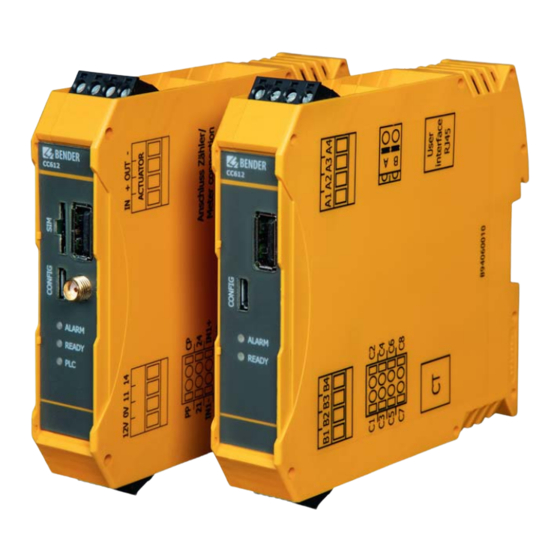
CC612 Laderegler/ CC612 charge controller
Legend
d
e
f
g
h
i
j
m
n
Other ways of connecting the charge controller can
be found in the operating manual.
i
The RJ45 user interface is not intended as an
Ethernet interface.
i
The use of Nano SIM cards with a correspon-
ding SIM card adapter may damage the SIM
card slot. Therefore, it is recommended
to
use
only
i
Further information on the connection can be
found in the manuals of the accessories (e.g.
W15BS).
• Connect PE to "0V"; reference level for Control
Pilot (CP communication) must be at the
same
level
(IEC 61851 series of standards).
• Connect Modbus (A, B) using a shielded
cable; connect shield to PE.
• Cable lengths (except Modbus, Ethernet,
Power IN and charging cable): < 3 m, cables
must be positioned inside the wallbox/char-
ging station and should not be laid parallel to
power cables.
CC612(4G)_D00325_06_Q_DEEN / 06.2021
Schütz
Typ-2-Buchse*
Typ-2 Stecker *
Anschluss Proximity Pilot
Anschluss Control Pilot
Relais 1: Steuerpin Schütz
Ausgang Relais 2
Optokopplereingang 1
Optokopplereingang 2
Micro
SIM
as
the
power
supply
cards.
5