Bender B95 012 004 Manual - Page 6
Browse online or download pdf Manual for Controller Bender B95 012 004. Bender B95 012 004 20 pages. Control and indicating device for ems and eds systems
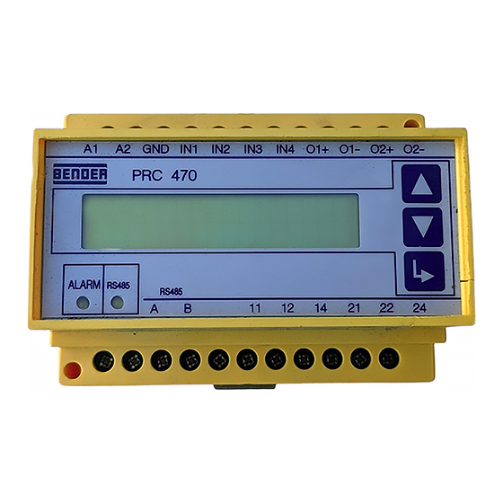
PRC470, PRC470E
Das Steuergerät PRC470 wird vorwiegend als Teil ei-
nes RCMS470- oder EDS47x-Systems mit allen not-
wendigen
Geräteeinstellungen
werkseitig eingestellten Parameter des Systems sind
im Prüfprotokoll dokumentiert.
Änderungen an diesen Parametern können die Funk-
tion des angeschlossenen Systems beinträchtigen.
Nehmen Sie Änderungen an den Geräteeinstellungen
nur nach Rücksprache mit BENDER vor! Notieren Sie
Ihre Einstellungen. Für das RCMS470-System finden
sie im Anhang eine Tabelle zur Dokumentation der
Einstellungen.
Hauptmenü
Das PRC470 passt sein Hauptmenü an das angeschlossene Sys-
tem an.
Hauptmenü im RCMS470-System:
m1: monitor
Zeigt Messwert, Adresse und Kanal im Alarmfall an.
m2: set Y
Einstellung von Ansprechwerten und einer Vorwarnung.
m3: test
Testet alle an den BMS-Bus angeschlossenen BENDER-Geräte.
m4: reset
Rücksetzen der Alarmrelais und Alarm-LEDs am PRC470 und an
allen angeschlossenen RCMS470-12 bzw. EDS47x-12.
m5: position
Zeigt ständig den Messwert eines ausgewählten Messstrom-
wandlerabgangs an.
m6: relais
Einstellung der Arbeitsweise der Alarmrelais aller am BMS-Bus
angeschlossenen Geräte.
m7: memory
Einstellung des Speicherverhaltens aller am BMS-Bus ange-
schlossenen Auswertegeräte RCMS470-12 bzw. EDS47x-12.
m8: factor
Einstellung eines Faktors zur Anpassung des RCMS470-12 an
angeschlossene Messstromwandler.
m9: conn.CT
Überwachung der Messstromwandlereingänge ein- oder aus-
schalten.
m10: function
Messstromwandlereingänge auf Überstrom- bzw. Unterstrom-
funktion einstellen oder ausschalten.
Hauptmenü im EDS47x-System:
Die folgenden Untermenüs sind abweichend gegenüber dem
Hauptmenü des RCMS-Systems
m2: EDS start
Zum manuellem Start der Isolationsfehlersuche
m8: Sensor
Einstellung für jeden Kanal, ob ein Standardwandler, ein teil-
barer Wandler oder kein Wandler angeschlossen ist.
m10: n-peak
Sichert eine wirksame Isolationsfehlersuche. Für jeden Wand-
ler wird eingestellt, wie oft die Messung bei auftretenden Stö-
rungen wiederholt wird.
6
geliefert.
Alle
Main menu
The PRC470 adapts its main menu in line with the connected
system.
Main menu in RCMS470 system:
m1: monitor
m2: set Y
m3: test
m4: reset
m5: position
m6: relais
m7: memory
m8: factor
m9: conn.CT
m10: function
Main menu in the EDS47x system:
The following submenus deviate from the main menu of the
RCMS system
m2: EDS start
m8: Sensor
m10: n-peak
The control device PRC470 is supplied with all the
necessary device settings, primarily as part of an
RCMS470 or EDS47x system. All of the systems
parameters that are set at the factory are
documented in the test report.
Any changes made to these parameters could affect
the functionality of the connected system. The device
settings should only be changed after consultation
with BENDER! Please make a note of your settings. A
table has been provided in the appendix for docu-
menting the settings of the RCMS470 system.
Shows measurement value, address and channel in the event
of an alarm.
Setting of response values and prewarning.
Tests all BENDER devices connected to the BMS bus.
Resets the alarm relays and alarm LEDs on the PRC470 and on
all connected RCMS470-12 and EDS47x-12.
Continuously indicates the measurement value of a selected
measuring current transformer subcircuit.
Sets the operation of the alarm relays of all devices connected
to the BMS bus.
Sets the storage properties of all evaluators RCMS470-12 and
EDS47x-12 that are connected to the BMS bus.
Sets the factor to adapt the RCMS470-12 to the connected
measuring current transformer.
Switches monitoring of the measuring current transformer
inputs on and off.
Sets or deactivates measuring current transformer inputs for
overcurrent or undercurrent function.
For the manual start of insulation fault location
Setting for each channel as to whether a standard transformer,
a separable transformer or no transformer is connected.
Guarantees effective insulation fault location. The number of
times the measurement should be repeated in the event of a
fault is set for each transformer.
108001 / 11.2004