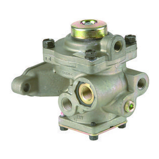
BENDIX R-7 MODULATING VALVE Manual - Page 5
Browse online or download pdf Manual for Control Unit BENDIX R-7 MODULATING VALVE. BENDIX R-7 MODULATING VALVE 6 pages. Modulating valve

ASSEMBLY
Before assembly, lightly lubricate all o-rings, bores and
mating surfaces with silicone lubricant BW-650-M (Bendix
Pc. No. 291126).
1. Install single check valve assembly and allen head plug.
Tighten securely.
2. Install o-ring on supply adapter, install shuttle guide over
supply adapter and install double check valve in guide.
3. Install adapter and double check valve assembly in
supply port. Install retaining ring, making certain the
retaining ring is engaged in groove.
4. Install o-ring on balance piston and install balance piston
in bore of body.
5. Install inner and outer springs and spring seat (note
that cone shaped protrusion on spring seat faces
springs).
6. Install cover with four (4) cap screws, torque to
approximately 45 in. lbs.
screw unless spring brake hold-off pressure is to be
adjusted. See section "Adjustment of Modulating
Valve").
7. Install valve on valve body. Install valve retainer, spring,
and washer. Install o-ring on o-ring retainer. Install
o-ring retainer, compress retainer and install retaining
ring, making certain retaining ring is engaged in groove
of valve body.
8. Install inlet/exhaust valve assembly in body. Install
retaining ring making certain the retaining ring is engaged
in groove in bore of body.
9. Install three (3) o-rings on control piston. Install control
piston in body. (Larger diameter stem should point up).
10. Install o-ring on cover. Install cover with four (4) cap
screws and lockwashers. Torque to approximately 100
in. lbs.
11. Install exhaust diaphragm and exhaust cover.
TESTING REBUILT R-7
Perform operating and leakage tests as outlined in "Service
Tests" section.
(Do not disturb center cap
™
MODULATING VALVE
5
