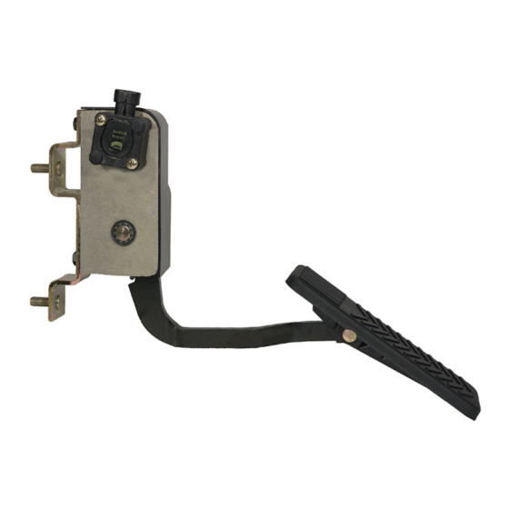
BENDIX ET-S Manual - Page 6
Browse online or download pdf Manual for Automobile Parts BENDIX ET-S. BENDIX ET-S 8 pages. Suspended electronic treadle

b. Connect the potentiometer or position sensor to the volt
meter and power supply as shown in Figures 6, 7 or 8,
depending on the model. Note: The power supply needs
to be 5 VDC. Do not exceed this voltage.
c. Verify that the closed throttle (idle) output voltage, as a
percentage of supply voltage, is within the limits listed
in Figure 2. For example, with a supply voltage of 5
volts, for the Caterpillar potentiometer in its closed throttle
position, read between 0.5 to 1.0 volts (10%-20% of
supplied voltage).
d. Depress the treadle to its full throttle position. The output
voltage, as a percentage of supply voltage, should be
within the limits listed in Figure 2. For example, with a
supply voltage of 5 volts, for the Caterpillar position
sensor in its open throttle position, read between 3.75
to 4.5 volts (75-90% of supplied voltage).
e. Make five full applications and record idle position voltage
each time. Verify that idle position voltages recorded do
not vary by more than .4% (For example, for a 5 volt
supply, if there is any variation, the difference between
the high and low readings should not exceed .02 volts).
If the electronic treadle fails to function within its specified
ranges, it should be repaired or replaced with a new or
genuine Bendix remanufactured unit, available at any
authorized parts outlet.
Treadle Installation:
™
ET-S
Treadle
1. Replace the rubber treadle cover if needed.
2. Place the spring (7) on the treadle pivot pin.
3. Install the nyliner bearing (6) into the treadle. Note: the
nyliner bearing collar is placed on the treadle arm side.
Holding the spring in position, the treadle is then in-
stalled. The nylon washer (4) and retaining ring (3) secure
the treadle into position.
™
4. Make sure the ET-S
movement.
5. Install the ET-S
™
treadle on the vehicle (see ET-S
ET-S2
™
Treadle Installation).
ET-S2
™
Treadle
1. Position the treadle assembly on its side with the poten-
tiometer facing up.
2. Insert the nyliner bearing (6) into the treadle arm with the
collar up (toward potentiometer side). The nyliner bear-
ing (6) will protrude through the treadle arm providing a
guide for the treadle spring (7).
3. Place the treadle spring (7) on the protruding portion of the
nyliner bearing with the tangs of the treadle spring (7) point-
™
ing toward the ET-S2
rest on the top side of the treadle arm. Align the treadle
arm and treadle spring with the recess in the underside of
the treadle.
6
treadle has a smooth, even treadle
treadle body. The short tang should
4. Insert the pivot pin from the potentiometer side of the
™
ET-S2
treadle assembly through the treadle, treadle
arm, nyliner bearing (6) and spring (7). Secure with the
nylon washer (4) and retaining ring (3).
5. Make sure the ET-S2
movement.
6. Install the ET-S2
ET-S2
™
Treadle Installation).
™
ET-S
& ET-S2
1. Using the mounting hardware set aside, install the
assembled electronic treadle on the vehicle. Torque to
between 85 and 110 lb. in.
2. Reconnect the cable connector by plugging it into the
potentiometer's integral connector and pushing until the
lock tab snaps into place.
WARNING! PLEASE READ AND FOLLOW
THESE
INSTRUCTIONS
PERSONAL INJURY OR DEATH:
When working on or around a vehicle, the following
general precautions should be observed at all times.
1. Park the vehicle on a level surface, apply the
parking brakes, and always block the wheels.
Always wear safety glasses.
2. Stop the engine and remove ignition key when
working under or around the vehicle. When
working in the engine compartment, the engine
should be shut off and the ignition key should be
removed. Where circumstances require that the
engine be in operation, EXTREME CAUTION should
be used to prevent personal injury resulting from
contact with moving, rotating, leaking, heated or
electrically charged components.
3. Do not attempt to install, remove, disassemble or
assemble a component until you have read and
thoroughly understand the recommended
procedures. Use only the proper tools and observe
all precautions pertaining to use of those tools.
™
&
4. If the work is being performed on the vehicle's air
brake system, or any auxiliary pressurized air
systems, make certain to drain the air pressure from
all reservoirs before beginning ANY work on the
vehicle. If the vehicle is equipped with an AD-IS
air dryer system or a dryer reservoir module, be
sure to drain the purge reservoir.
5. Following
recommended procedures, deactivate the electrical
system in a manner that safely removes all
electrical power from the vehicle.
6. Never exceed manufacturer's recommended
pressures.
7. Never connect or disconnect a hose or line
containing pressure; it may whip. Never remove a
component or plug unless you are certain all
system pressure has been depleted.
™
treadle has smooth, even treadle
™
treadle on the vehicle (see ET-S
™
TREADLE INSTALLATION
TO
the
vehicle
manufacturer's
™
&
AVOID
™
