GAC ESD5131H Quick Start Manual - Page 3
Browse online or download pdf Quick Start Manual for Control Unit GAC ESD5131H. GAC ESD5131H 6 pages. Speed control unit
Although it is difficult to predict levels of interference, appli-
cations that include magnetos, solid sate ignition systems,
radio transmitters, voltage regulators or battery chargers
should be considered suspect as possible interfering sourc-
es.
If it is suspected that external fields, either those that are
radiated or conducted, are or will affect the governor sys-
tems operation, it is recommended to use shielded cable for
all external connections. Be sure that only one end of the
shields, including the speed sensor shield, is connected to a
single point on the case of the speed control unit. Mount the
speed control to a grounded metal back plate or place it in a
sealed metal box.
Radiation is when the interfering signal is radiated directly
through space to the governing system. To isolate the gover-
nor system electronics from this type of interference source,
a metal shield or a solid metal container is usually effective.
Conduction is when the interfering signal is conducted
through the interconnecting wiring to the governor system
electronics. Shielded cables and installing filters are com-
mon remedies.
In severe high-energy interference locations such as when
the governor system is directly in the field of a powerful
transmitting source, the shielding may require to be a spe-
cial EMI class shielding. For these conditions, contact GAC
application engineering for specific recommendations.
Instability in a closed loop speed control system can be
categorized into two general types. PERIODIC appears to
be sinusoidal and at a regular rate. NON-PERIODIC is a
random wandering or an occasional deviation from a steady
state band for no apparent reason.
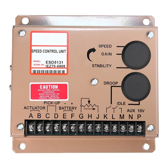
The ESD5131 Sped Control Unit was derived from the stan-
dard GAC ESD5111 Speed Control Unit. All specifications,
installation procedures, and adjustments, except those not-
ed are identical.
The difference between the ESD5131 and the ESD5111 lies
in the two DIP switches located under the upper access hole.
Switch 1 controls the "Lead Circuit" found in the ESD5111.
The normal position is "ON." Move the switch to the "OFF"
position if there is fast instability in the system.
Switch 2 controls an additional circuit added in the ESD5131
that is designed to eliminate fast erratic governor behav-
ior, caused by very soft or worn couplings in the drive train
between the engine and generator. The normal position is
"OFF." Move to the "ON" position if fast erratic engine behav-
ior due to a soft coupling is experienced.
The PERIODIC type can be further classified as fast or slow
instability. Fast instability is a 3 Hz. or faster irregularity of
the speed and is usually a jitter. Slow periodic instability is
below 3 Hz., can be very slow, and is sometimes violent.
If fast instability occurs, this is typically the governor respond-
ing to engine firings. Raising the engine speed increases the
Instability
This document is subject to change without notice.
Caution: None of GAC products are flight certified controls including this item.
frequency of instability and vice versa. In this case, the re-
moval of E6 to E7 jumper will reduce the speed control unit's
sensitivity to high frequency signals. Readjust the GAIN
and STABILITY 1 or optimum control. Should instability still
be present, the removal of E1 to E2 jumper may help stabi-
lize the engine. Post locations are illustrated in Diagram 2.
Again, readjust the GAIN and STABILITY for optimum con-
trol. Interference from powerful electrical signals can also be
the cause. Turn off the battery chargers or other electrical
equipment to see if the system instability disappears.
Slow instability can have many causes. Adjustment of the
GAIN and STABILITY usually cures most situations by
matching the speed control unit dynamics. If this is unsuc-
cessful, the dead time compensation can be modified. Add
a capacitor from posts E2 to E3 (negative on E2). Post lo-
cations are illustrated in Diagram 2. Start with 10 mfds, and
increase until instability is eliminated. The control system
can also be optimized for best performance by following this
procedure.
If slow instability is unaffected by this procedure, evaluate
the fuel system and engine performance. Check the fuel
system linkage for binding, high friction, or poor linkage. Be
sure to check linkage during engine operation. Also look at
the engine fuel system. Irregularities with carburetion or fuel
injection systems can change engine power with a constant
throttle setting. This can result in speed deviations beyond
the control of the governor system. Adding a small amount
of droop can help stabilize the system for troubleshooting.
NON-PERIODIC instability should respond to the GAIN con-
trol. If increasing the gain reduces the instability, then the
problem is probably with the engine. Higher gain allows the
governor to respond faster and correct for disturbance. Look
for engine misfirings, an erratic fuel system, or load changes
on the engine generator set voltage regulator. If the throttle
is slightly erratic, but performance is fast, removing the jump-
er from E6 to E7 will tend to steady the system.
If unsuccessful in solving instability, contact GAC for assis-
tance.
3
PIB1000 C