Gage Bilt GB2600A Original Instructions Manual - Page 11
Browse online or download pdf Original Instructions Manual for Power Tool Gage Bilt GB2600A. Gage Bilt GB2600A 16 pages. Installation tool
Providing all maintenance conditions have been met, follow this systematic approach to diagnosis.
1. NO OPERATION WHEN ELECTRIC ACTUATOR (240122) / AIR ACTUATOR ASSY (240123) IS DEPRESSED.
a.) Check Power unit power source.
b.) Control cord may be loose or damaged.
c.) Faulty ACTUATOR. Replace.
d.) Check hydraulic couplings; repair or replace.
2. SLOW OR PARTIAL OPERATION WHEN ELECTRIC ACTUATOR (240122) / AIR ACTUATOR ASSY (240123) IS DEPRESSED.
a.) Low hydraulic pressure. Check power unit, adjust.
b.) Glyd Ring (260124) on the piston assy (260011) could be worn or damaged. Replace.
c.) Excessive wear or scoring on moving parts. Check and replace faulty parts.
d.) Check hydraulic couplings; repair or replace.
3. TOOL OPERATES IN REVERSE.
a.) Tool stops in back position. Hydraulic hoses are reversed. Correct.
4. HYDRAULIC OIL OVERHEATS.
a.) Power unit motor rotation reversed. Electrical connections reversed. See power unit instruction manual.
b.) Restrictions in either hydraulic lines, hoses or couplings. Check and tighten, clean or replace. (See hydraulic thread preparation pg.10).
5. OIL LEAKAGE.
a.) Hydraulic oil leaks from connections. Tighten threaded connections. Do not use Teflon® tape. (See hydraulic thread preparation pg.10).
b.) Oil leaks from tool. Determine source of leak and replace worn or defective o'rings and back-up rings.
6. PINTAIL GROOVES STRIPPED DURING PULL STROKE.
a.) Nose Assembly must be pushed onto fastener fully.
b.) Chips may have collected in chuck jaws. Disassemble nose assembly, clean jaws in mineral spirits using a sharp pointed object.
c.) Chuck jaws may be worn or damaged. Replace.
d.) Pintail too short for jaws to properly grip. Select proper grip length fastener.
e.) Excessive gap between sheets. Reduce gap before attempting to install fastener.
7. NOSE ASSEMBLY WON'T ACCEPT FASTENER PINTAIL.
a.) Spent fastener stem may be jammed in pulling head. Disassemble and check for worn or broken parts in nose assembly.
Replace defective parts and clean before reassembling.
WARNING:
Disconnect the tool from power source when adding or removing relief valves.
1. Insert relief valve into piston with 4 flats facing rear of tool (See image below). DO NOT insert into piston with 4 flats facing the opposite
way or damage to the tool or personal injury can occur.
Front of Tool
GB2600 / GB2600A INTALLATION TOOL S/N: 1001 AND ABOVE
PLEASE CONTACT GAGE BILT FOR ALL OTHER SERIAL NUMBERS
TROUBLESHOOTING
RELIEF VALVE - INSTALLATION
Rear of Tool
INCORRECT
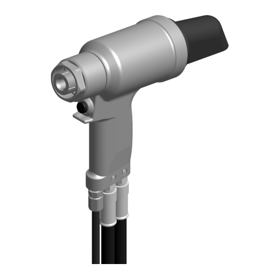
Images may not reflect actual tool
11
Position relief valve 4 flats
towards REAR of tool.
REV 1/20