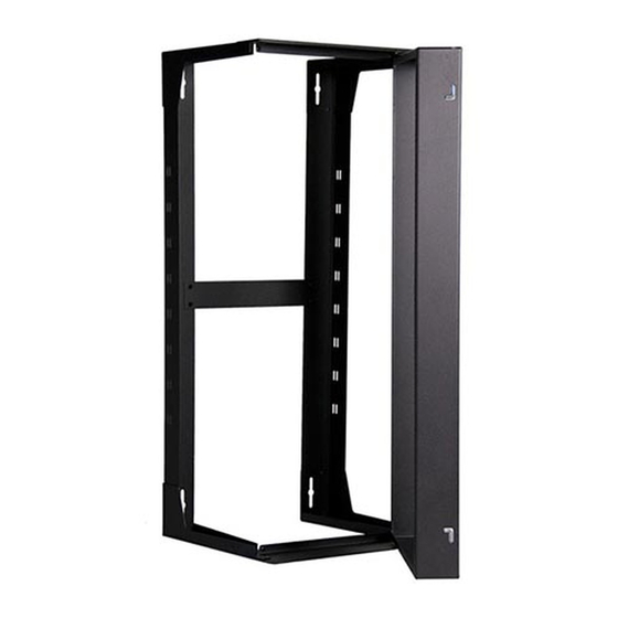
Great Lakes GL24SR Installation Instructions Manual - Page 6
Browse online or download pdf Installation Instructions Manual for Racks & Stands Great Lakes GL24SR. Great Lakes GL24SR 12 pages. 19" eia wall mount swing rack
Also for Great Lakes GL24SR: Installation Instructions Manual (8 pages)

STEP 2
Mount the rear assembly to the wall with four lag screws (not provided).
Mounting locations are as shown.
Install the 19" EIA Swing Frame by retracting both pins. The pins can be locked
out for ease of assembly by retracting the outside pin into the slot provided.
The retractable pins are to be near the front of the Swing Frame when
installing.
Release the lower pin then, align the top pin to the top receptacle and release
pin. Place 1/4-20 Screw through the hole in bottom (opposite pin hinge).
Assemble spacer on exposed threads on inside of swing rack and close swing
frame. Tighten screw by screwing into pem nut in Swing Frame. Repeat screw/
spacer assembly for top. Finally, tighten 8 screws on the top and bottom
braces.
8
Install ground lug and jumper wire as shown in Detail A and B.
D
C
Mounting
Location;
2 on top,
2 on bottom
B
Receptacles for
Pivot Pins: 1 in
top, 1 in bottom
A
3
2
8
DETAIL A
Earthing
Symbol
6
7
4
1/4-20 keps nut
1
7
DETAIL A
SCALE 1.5
6
3
1/4-20 x 5/8" Phil
Pan Head Screw
Ground
Lug
A
Retractable Pivot Pins; 1 on top, 1 on bottom
6
DETAIL B
D
Ground
Lug
B
C
5
4
1/4-20 x 3/4" Flat Head
Screw
1/4-20 Nylon
2
Locking Pellet
Ground
Wire
DETAIL A
SCALE 1.5
5
4
DETAIL B
SCALE 0.90 : 1
3
1
D
C
B
B
3
1/4-20 bolt
B
1/4-20
keps nut
Jumper Wire
1/4-20 keps nut
A
D
SCA
