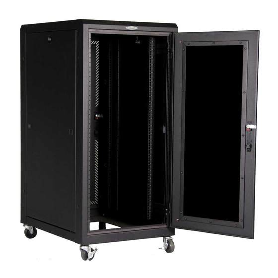
Great Lakes UL2416 E Series Installation Instructions Manual - Page 7
Browse online or download pdf Installation Instructions Manual for Enclosure Great Lakes UL2416 E Series. Great Lakes UL2416 E Series 13 pages. Equipment cabinet/rack

CASTER AND LEVELER MOUNTING
CAUTION
• To install casters or levelers the cabinet must be tipped onto its
side. The cabinet can be very heavy, several people will be
required in this process. Please practice safe lifting techniques.
• DO NOT lay the cabinet on its front or back, this may damage the
door hinges.
• Removing doors and sides will help reduce the weight of the
cabinet.
• Before tipping, remove the side panels to prevent damage to the
locks and latches.
CASTER MOUNTING
On the bottom of the cabinet there are eight threaded holes, two in
each corner. The holes are threaded 1/2"-13 thds. and will accept the
levelers provided. Once the levelers are installed,the cabinet level can
be adjusted with the use of a 3/4" open-end wrench. If ordered with
casters, two will have brakes that can be actuated by turning the brake
lever on the side of the wheel. The four inside holes in each corner are
meant to accept the casters. Be sure to thread the caster all the way
into the bottom of the cabinet until it is firmly seated.
BOTTOM VIEW
OF Cabinet
Through Holes (4)
11/16 Dia.
(4) Adjustable
Levelers
Counter clockwise rotation will
adjust the leveling glide up
Note: If you want to use casters AND leveling glides you will need 4" levelers.
ANCHOR MOUNTING THRU HOLE
The middle .687 dia. thru holes are for securing the cabinet to the
floor. These holes will accept a standard concrete anchor if desired; the
Seismic Anchor Kit (AK101) is suggested.
Threaded Holes
1/2" - 13 Thds.
Swivel
Casters (2)
Swivel Caster
w/ lock (2)
Clockwise rotation will adjust
the leveling glide down
7
