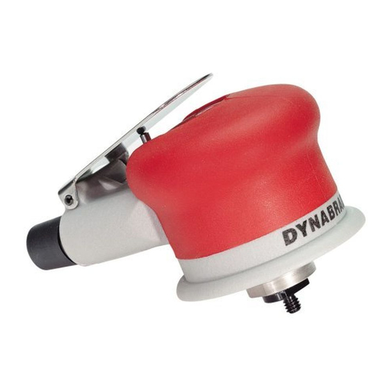
Dynabrade 10391 Operating, Maintenance And Safety Instructions - Page 3
Browse online or download pdf Operating, Maintenance And Safety Instructions for Sander Dynabrade 10391. Dynabrade 10391 4 pages. Palm-style buffer/sander air-powered, 2,400 rpm

Disassembly/Assembly Instructions - Palm-Style Buffer Sander
Important: Manufacturer's warranty is void if tool is disassembled before warranty expires.
A Motor Repair Kit (96046) is available which contains special tools for disassembly/assembly. Please refer to parts breakdown for part identification.
Motor Disassembly:
1. Invert machine and secure in vise, using 57092 Collar (supplied in 96046 Repair Kit) or padded jaws.
2. Remove any accessories attached to 54021 Adapter.
3. Insert 56058 Lock Ring Wrench (supplied in 96046 Repair Kit) into corresponding tabs of lock ring and unscrew. Motor may now be lifted
out for service.
4. Remove lock-ring, washer, front ring and rear ring from motor.
5. Remove 54021 Adapter by removing 95593 Set Screw using 5/64" allen wrench (supplied in 96046 Repair Kit). Place allen wrench into set screw hole
to stop rotation of 54465 Planetary Carrier. Use a 14 mm wrench to unscrew adapter (supplied in 96046 Repair Kit).
6. Remove 54467 Retaining Ring using two (2) 50679 26 mm wrenches (supplied in 96046 Repair Kit).
7. Remove 54465 Planetary Carrier by pressing out from 01139 Bearing. 06213 Gears can now be removed from planetary carrier.
8. Remove 54468 Ring Gear by tapping retaining ring on a hard surface, once the ring gear slides towards the front, it will be necessary to use your fingers
to remove it the rest of the way. Note: If hard to remove, heat may be applied to retaining ring and pliers used to remove gear the rest of the way.
9. Press 01139 Bearing from 54467 Retaining Ring.
10. Remove 57056 Rear Plate by holding onto 57058 Cylinder (bearing puller may be placed into exhaust slots on cylinder) and pressing 54470 Rotor
Pinion out of 01206 Bearing.
11. Remove 54491 Rotor/Blade Set. Remove 56047 Rotor Key.
12. Disassemble 57437 Front Plate by pressing 54470 Rotor Pinion through front plate. Note: One 01139 Bearing will remain on rotor pinion. To remove,
press pinion through remaining bearing.
13. Press 01206 Rear Bearing from 57056 Rear Bearing Plate.
Motor Disassembly Complete.
To Assemble:
Important: Be certain all parts are clean and in good repair before assembling.
1. Press 01139 Bearing onto rotor pinion until seated against shoulder.
2. Press bearing/rotor pinion assembly into 57437 Front Plate and check for smooth rotation.
3. Place 07146 Packing in front plate bore and press 01139 Bearing into bore onto packing.
4. Invert rotor pinion in support. Install 56047 Rotor Key and 54491 Rotor/Blade Set onto rotor pinion.
Important: Place the correct number of shims from the 95975 Shim Pack under rotor to achieve a 0.0015" space between rotor and front plate.
Note: Blades should be lightly lubricated with Dynabrade Air Lube P/N 95842 (or equivalent) before installation into rotor slots.
5. Place 57058 Cylinder Assembly over rotor. The "short" line-up pin goes toward the front plate.
6. Place 57056 Rear Plate (with 01206 Bearing pressed into place) over shaft and "long" end of line-up pin. Press fit in place.
7. Press 01139 Bearing into 54467 Retaining Ring.
8. Place 54468 Ring Gear into 54467 Retaining Ring lining up one of the notches with set screw hole.
9. Place 54465 Planetary Carrier with 06213 Gears and 54475 Shafts in place into 54467 Retaining Ring (1/4"-28 female thread, facing down).
Note: Gears should be lightly greased with Dynabrade's 95542 Grease (or equivalent).
10. Align 54465 Planetary Carrier with splined end of 54470 Rotor Shaft.
11. Screw retaining ring assembly onto front plate and tighten using (2) 26 mm wrenches.
12. Place 5/64" allen wrench into retaining ring set screw hole and tighten 54021 Adapter with 14 mm wrench.
13. Hand tighten 95593 Set Screw in place using 5/64" allen wrench. Note: Be sure notch on ring gear is lined up with set screw hole.
14. Place 57054 Rear Ring over the rear plate and line-up pin. Turn motor over and install 57055 Front Ring over front plate. Make sure the "legs and
fingers" on the rings line-up. Also, the small cut-outs on both rings should line-up with the square holes in the cylinder/end plate assembly.
15. Secure motor housing in vice using 57092 Collar or padded jaws. Slide motor assembly into housing. Note: Be certain line-up pin enters the line-up
hole at bottom of housing bore and the "legs" of the rings stay in-line.
16. Place 95973 washer and 57059 Lock Ring onto the Front Ring with 1 drop of pneumatic tool oil spread between the washer and lock ring. Tighten lock
ring with 56058 Lock Ring Wrench torque to 28 N•m/250 in. - lbs.
17. Attach desired accessory to adapter.
Tool Assembly Complete. Please allow 30 minutes for adhesives to cure before operating tool.
Important: Motor should now be tested for proper operation at 90 PSIG. If motor does not operate properly or operates at a higher RPM than marked on the
tool, the tool should be serviced to correct the cause before use. Before operating, place 2-3 drops of Dynabrade Air Lube (P/N 95842) directly into air inlet
with throttle lever depressed. Operate tool for 30 seconds to determine if tool is operating properly and to allow lubricating oils to properly penetrate motor
Loctite
®
is a registered trademark of Loctite Corp.
3
