Hi-Par HP315E Control User Manual
Browse online or download pdf User Manual for Control Unit Hi-Par HP315E Control. Hi-Par HP315E Control 2 pages. Cmh controllable ballast
Installation Directions
1. Digital Ballast
6. Rubber Feet
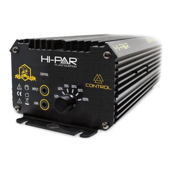
7. Dimming Knob
8. Connect
Link Cable
STATUS
LED
Output lock down
1 Flash
Output errors
2 Flash
Low input voltage
3 Flash
Over temperature
4 Flash
High input
5 Flash
Note: When the controller is connected the CONTROL indicator LED ashes 2 times every 2
seconds - indicating controller is functioning correctly. However, if the Connect Link Cable is
removed during operation the ballast will shut down after 3 minutes. When operating
ballast without a HI-PAR Control Station the CONTROL indicator LED will be o . Turn power
o and on to reset the ballast when either connecting or disconnecting the Control Station.
MAINS POWER
MIN
MAX
100%
315
347
90%
284
317
80%
250
284
70%
217
250
60%
184
217
50%
150
184
5. OUTPUT to
CMH lamp
4. Power Input
3. Magnet Ring
BOX CONTENTS:
1 x 315w Digital Ballast
1 x Power Cord
CMH Lamps ONLY
1 x Connect Link Cable
4 x Rubber Feet
1 x User Manual
LAMP POWER
MIN
MAX
100%
296
328
90%
267
300
80%
235
269
70%
204
237
60%
172
206
50%
140
174
2. Power
USER MANUAL
Cord
HP315E Control for CMH lamps
Data is based on operation of a standard CMH lamp.
Supply power is based on typical commercial 240V,50/60Hz.
Performance
Model
Model
Voltage
(V)
HP315E
240V
Control
Max Input
THD
Maximum
Power
Power
Current
Factor
(W)
(A)
(COSθ)
347
<10%
1.6
.97
Working
Ignitor
Voltage
Voltage
(V)
(kV)
216-264
4.0